

Electro-optic grating-coupled surface plasmon resonance (EOSPR)
Patent Information
- Authority / Receiving Office
- US · United States
- Patent Type
- Patents(United States)
- Current Assignee / Owner
- CIENCIA
- Publication Date
- 2016-07-05
Smart Images
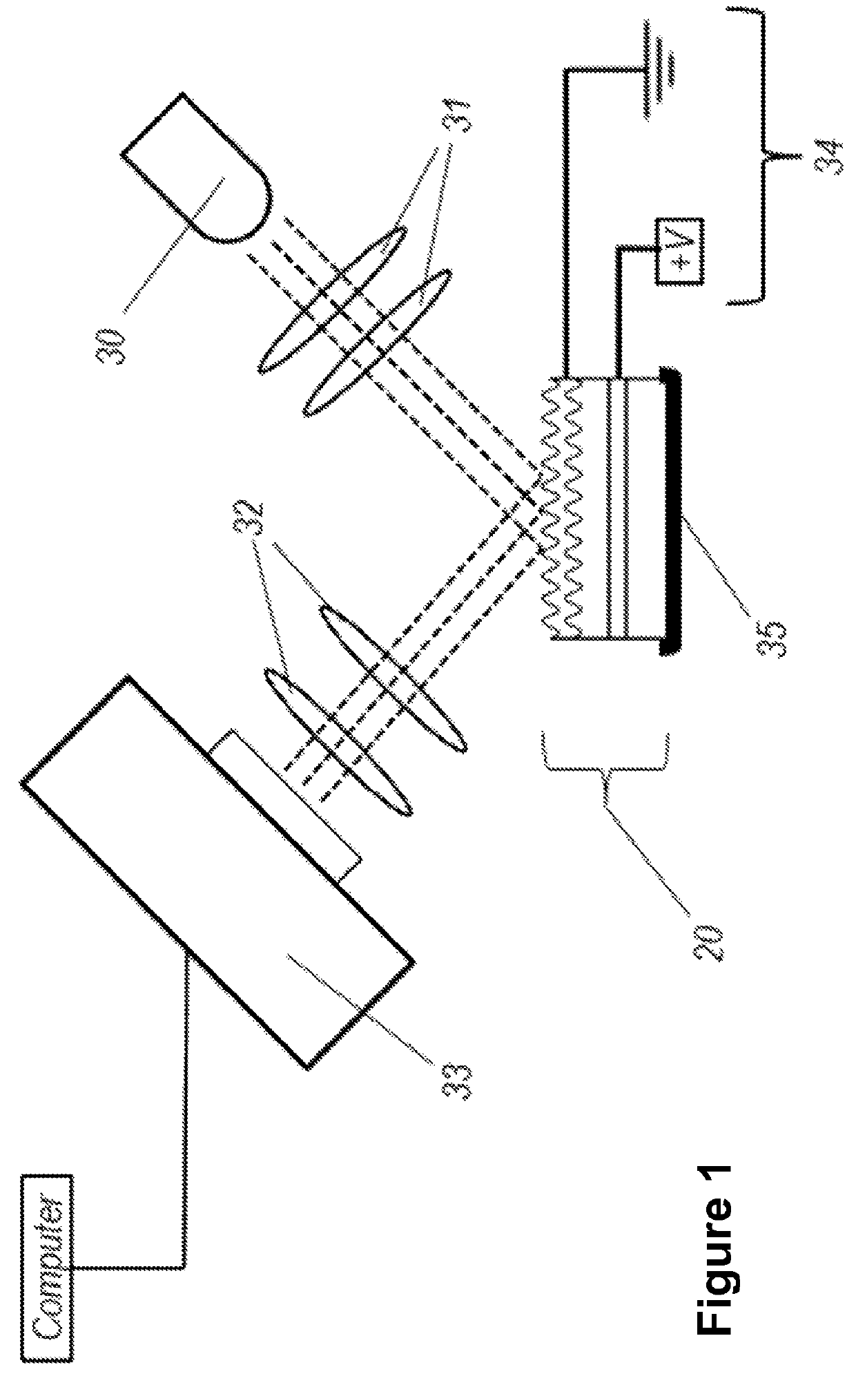
Figure 1 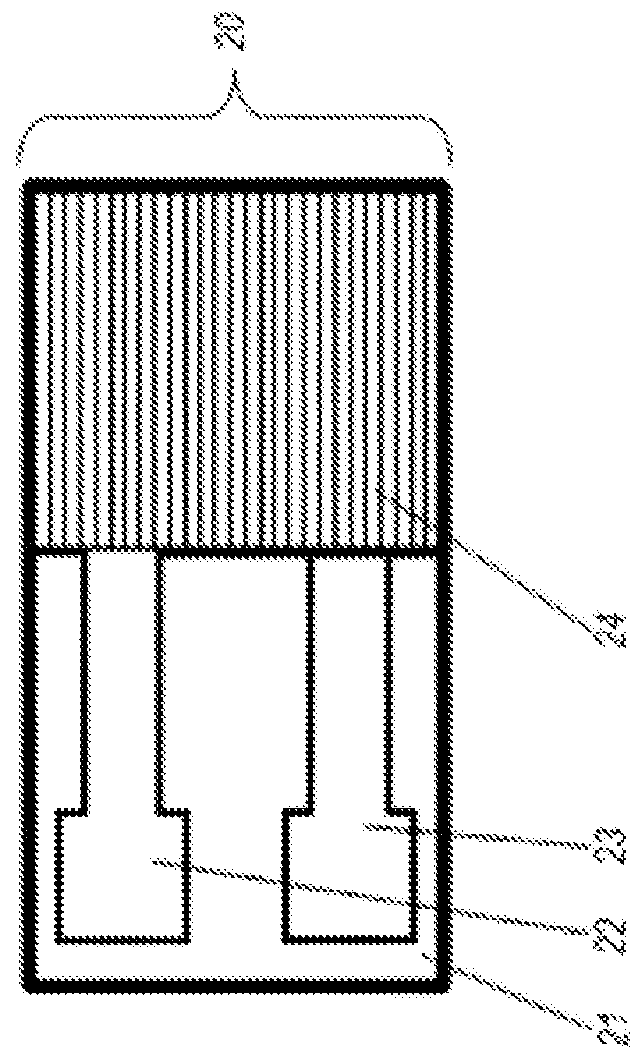
Figure 2 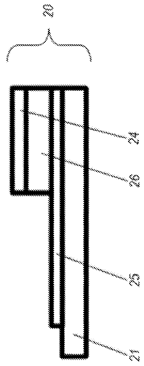
Figure 3
Abstract
Description
CROSS-REFERENCE TO RELATED APPLICATIONS
[0001] This application claims the benefit of U.S. Provisional Patent Application No. 61 / 900,548 for “Electro-Optic Grating-Coupled Surface Plasmon Resonance (EOSPR)”, filed Nov. 6, 2013, the disclosure of which is incorporated by reference in its entirety.STATEMENT REGARDING FEDERALLY SPONSORED RESEARCH OR DEVELOPMENT
[0002] This application is based on research and development done under NIH / NIGMS Grant No. 1R43GM104636-01.TECHNOLOGICAL FIELD
[0003] The described embodiments relate to an instrument and method for the detection, measurement, and characterization of a wide variety of specific molecules, simple or complex solutions, and biological cells.BACKGROUND OF THE INVENTION
[0004] Requirements for the identification and measurement of biological or chemical entities in a sample typically include a means of isolating or separating the analyte in question. Once spatially, temporally, or otherwise isolated from the surroundings, the analyte provide...