Control apparatus for power transmission system

a technology of power transmission system and control apparatus, which is applied in fluid gearings, transportation and packaging, and gearings, etc., can solve the problems of affecting the progress of the engagement process, the control of the engagement device may not be appropriately executed, and the increase in the electric power consumption of the electric oil pump

Active Publication Date: 2016-12-22
TOYOTA JIDOSHA KK
View PDF4 Cites 6 Cited by
  • Summary
  • Abstract
  • Description
  • Claims
  • Application Information

AI Technical Summary

Benefits of technology

[0011]With the control apparatus according to this aspect, the supply of hydraulic pressure to the second engagement device is set to zero at the time when the second control pressure is lower than or equal to the piston stroke end pressure in process of releasing the second engagement device. Therefore, it is possible to secure the first control pressure that is required to engage the first engagement device while preventing the second engagement device from being suddenly released.

Problems solved by technology

Incidentally, when the entire control pressure that is supplied to the engagement device is intended to be secured with the use of the electric oil pump, the electric power consumption and body size of the electric oil pump increase.
In this respect, as the discharge flow rate of the electric oil pump is reduced, there can be a case where a required control pressure is not secured at the time when the engagement device is engaged by using a hydraulic pressure from the electric oil pump, so control for engaging the engagement device may not be appropriately executed.
If the required control pressure is not secured during engagement of the engagement device, there is a concern that the progress of engaging process stagnates or the engaging process regresses toward a released state and then the engagement device is suddenly engaged at the time when the required control pressure is secured.
If this occurs during traveling, shock may occur.

Method used


Image

  • Control apparatus for power transmission system
  • Control apparatus for power transmission system
  • Control apparatus for power transmission system

Examples


Embodiment Construction

[0019]Hereinafter, an embodiment of the invention will be described in detail with reference to the accompanying drawings.

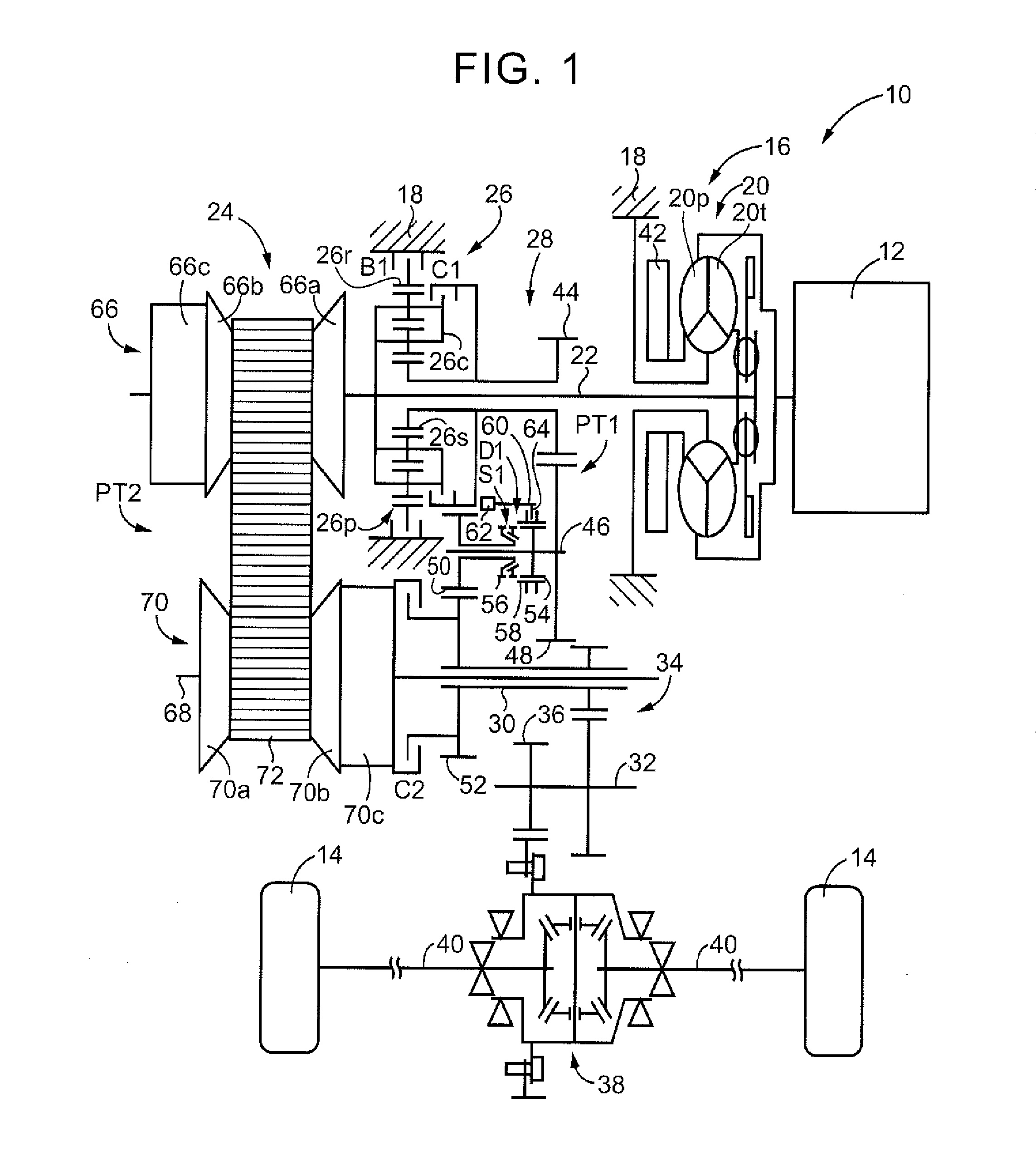
[0020]FIG. 1 is a view that illustrates the schematic configuration of a vehicle 10 to which the invention is applied. As shown in FIG. 1, the vehicle 10 includes an engine 12, drive wheels 14 and a power transmission system 16. The engine 12 functions as a driving force source for propelling the vehicle 10. The engine 12 is, for example, a gasoline engine or a diesel engine. The power transmission system 16 is provided between the engine 12 and the drive wheels 14. The power transmission system 16 includes a known torque converter 20, an input shaft 22, a known belt-type continuously variable transmission 24, a forward / reverse switching device 26, a gear transmission mechanism 28, an output shaft 30, a counter shaft 32, a reduction gear unit 34, a differential gear 38, a pair of axles 40, and the like, in a housing 18 that serves as a non-rotating member. The to...


PUM


Abstract

A control apparatus for a power transmission system is provided. The control apparatus includes an electronic control unit. The electronic control unit is configured to, when a discharge flow rate of a mechanical oil pump is smaller than a predetermined flow rate and an electric oil pump is being driven while a vehicle is traveling, determine whether a decrease in the operating hydraulic pressure has occurred. The electronic control unit is configured to, when a first engagement device is controlled from a released state toward an engaged state, control a first control pressure such that the first control pressure in a case where a decrease in a operating hydraulic pressure has occurred is lower than the first control pressure in a case where a decrease in the operating hydraulic pressure does not occur.

Description

INCORPORATION BY REFERENCE[0001]The disclosure of Japanese Patent Application No. 2015-121578 filed on Jun. 16, 2015 including the specification, drawings and abstract is incorporated herein by reference in its entirety.BACKGROUND OF THE INVENTION1. Field of the Invention[0002]The invention relates to a control apparatus for a power transmission system including a mechanical oil pump, an electric oil pump and an engagement device that is controlled to be engaged or released by using a hydraulic pressure that is discharged from the mechanical oil pump or the electric oil pump as a source.2. Description of Related Art[0003]There is well known a power transmission system including a mechanical oil pump, an electric oil pump and an engagement device that is controlled to be engaged or released by using a control pressure of which a source pressure is an operating hydraulic pressure based on a hydraulic pressure that is discharged from the mechanical oil pump or the electric oil pump. Th...

Claims


Application Information

Patent Timeline
Patent Type & Authority Applications(United States)
IPC IPC(8): F16D48/06F16H7/00F16H45/02F16D48/02F16D25/12
CPCF16D48/066F16D48/0206F16H2045/0215F16H45/02F16H7/00F16D25/12B60K17/02B60K17/04F16D48/062F16D2500/1026F16D2500/10412F16D2500/3024F16D2500/30806F16D2500/3108F16D2500/3111F16D2500/70406F16H61/0262F16H61/662F16H61/688B60W2710/023B60W30/18018
Inventor KIMURA, MOTONORIITOH, AKIHIDESAKAMOTO, KAZUYAKONDO, HIROKIFUKAO, MITSUHIROISHIIZUMI, KAZUYA
Owner TOYOTA JIDOSHA KK
Why Eureka
Try Eureka