Light with dynamic light pattern

Inactive Publication Date: 2017-02-09
CHEN TSAN YAO
View PDF7 Cites 3 Cited by
  • Summary
  • Abstract
  • Description
  • Claims
  • Application Information

AI Technical Summary

Benefits of technology

The present invention provides a light with dynamic light patterns that create a unique and engaging display based on the persistence of vision effect. The light includes a housing, a lighting unit, a mounting member, a gear set, a motor, a rotary disc, a circuit board unit, and a pattern layer set. The pattern layer set consists of a still outer pattern layer and an inner pattern layer close to the outer pattern layer. The inner pattern layer is disposed on and rotated along with the rotary disc, and the inner and outer pattern layers are arranged with patterns that match each other well. The dynamic light patterns displayed on the outer surface of the outer sleeve capture users' attention and enhance the market competitiveness of the light. The light can also be used as a speaker cabinet.

Problems solved by technology

However, the light pattern displayed is boring and dull due to limitations of internal structure.

Method used


Image

  • Light with dynamic light pattern
  • Light with dynamic light pattern
  • Light with dynamic light pattern

Examples


first embodiment

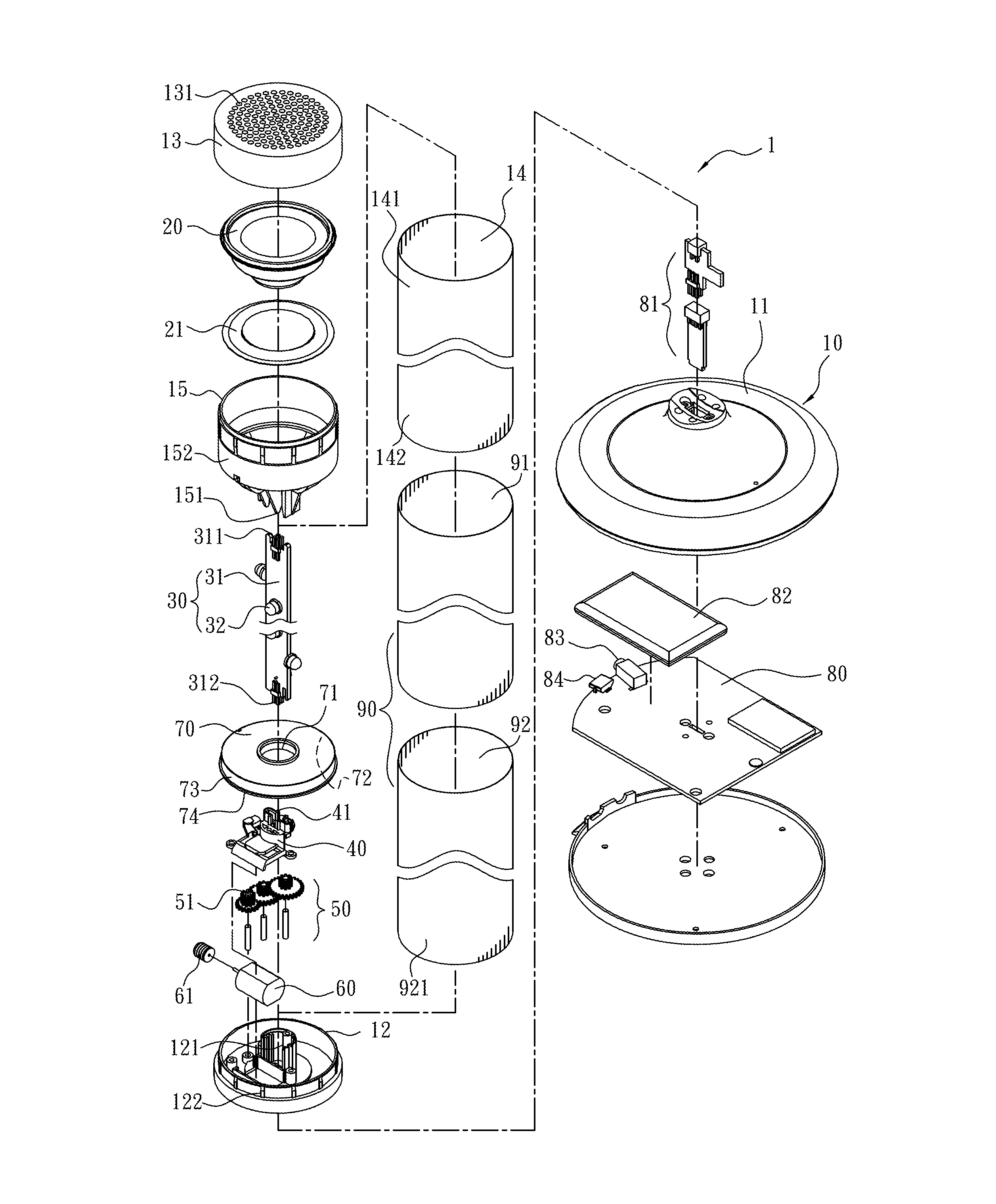
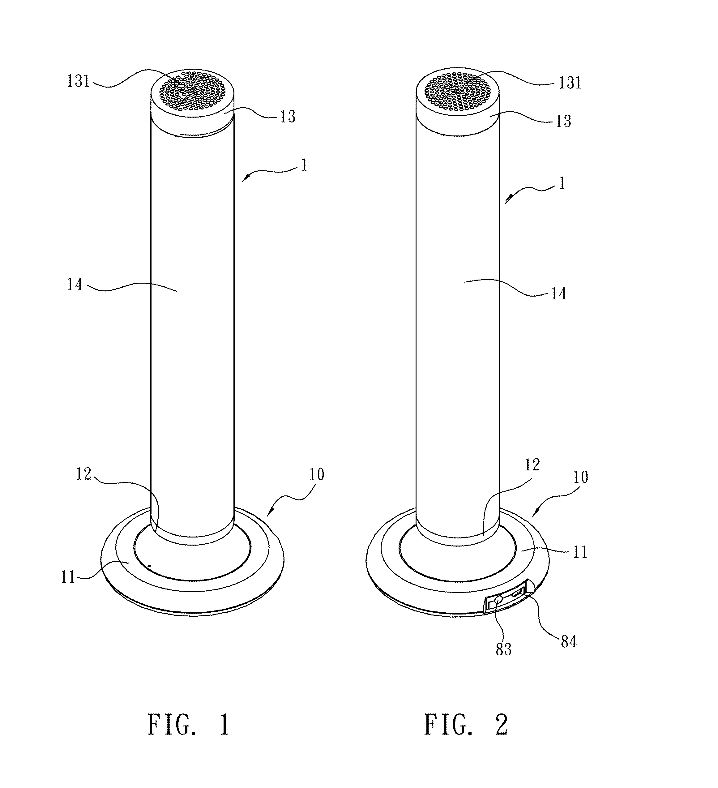
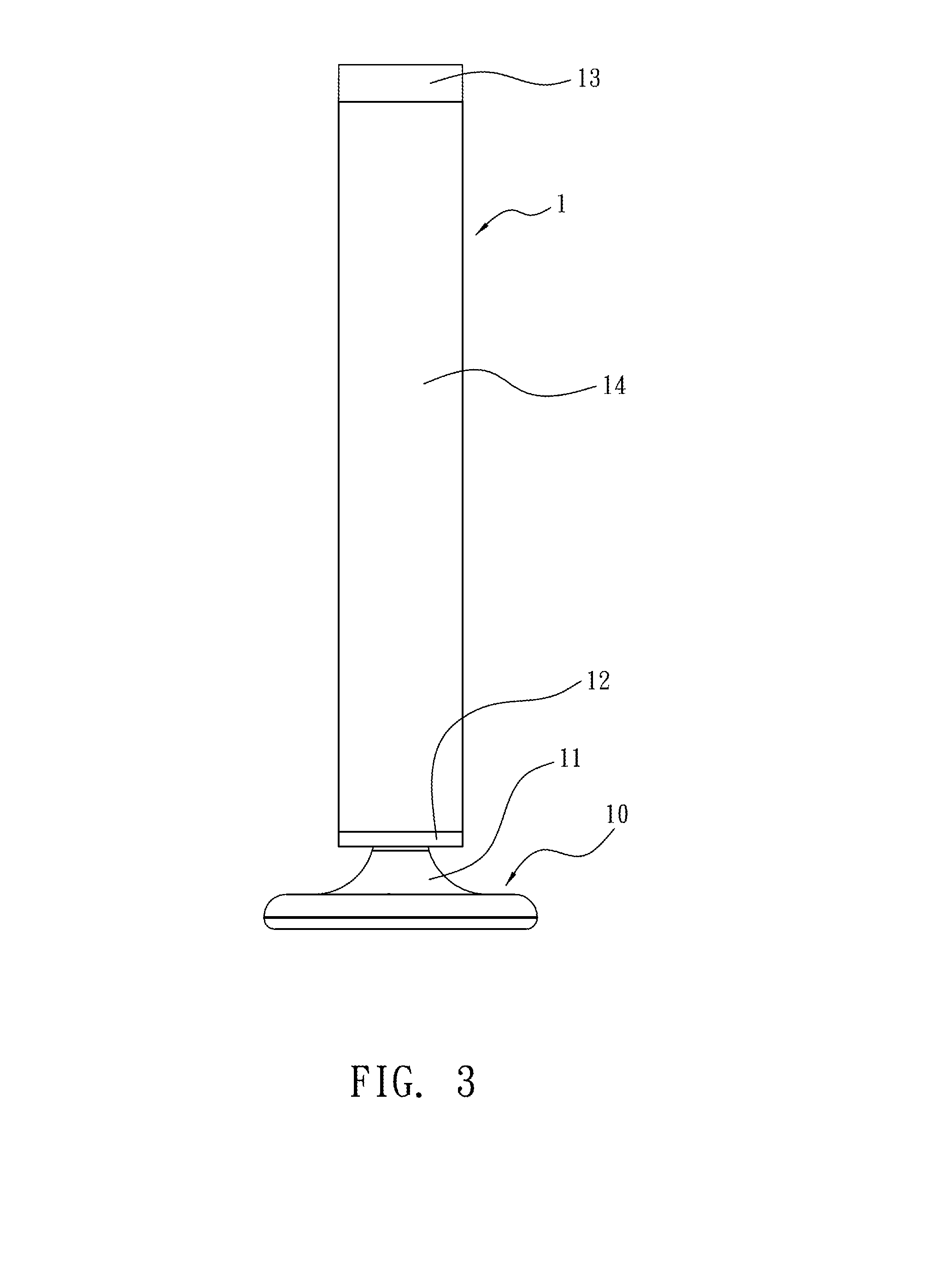
[0022]Refer from FIG. 1 to FIG. 6, the present invention is a vertical cylindrical light 1. Refer to FIG. 4, the light 1 of the present invention further includes an audio unit 20. The audio unit 20 is an optional accessory of the present invention. The light 1 of the present invention includes a housing 10, an audio unit 20, a lighting unit 30, a mounting member 40, a gear set 50, a motor 60, a rotary disc 70, a circuit board unit 80 and a cylindrical pattern layer set 90. The above components are drawn to scale.

[0023]In this embodiment, the housing 10 consists of a base 11, a first cap 12, a second cap 13, an outer sleeve 14, and a receiving member 15. The base 11 is used for standing on a plan surface such as a desk surface. A space inside the base 11 is used to mount the circuit board unit 80 and the related components such as a power supply unit 82, a power port 83 or a control port 84 such as USB port. The first cap 12 is connected to and disposed over the base 11 while a spac...

second embodiment

[0032]Refer to FIG. 12, FIG. 13, and FIG. 14, another embodiment is revealed. The second embodiment is a horizontal cylindrical light 2. This embodiment has the same technical features (such as used as a speaker cabinet) as the above embodiment. The difference between this embodiment and the one shown in FIG. 1 to FIG. 6 is in that this embodiment includes two vertical cylindrical lights I connected to each other and arranged horizontally. For simplifying structure and reducing cost, a part of components of the vertical cylindrical lights (1) on the left side and the right side respectively can use the same one component. For example, the horizontal cylindrical light 2 includes a base 11, a first cap 12, two second caps 13, two outer sleeves 14, two receiving members 15, two audio units 20, two lighting units 30, a mounting member 40, a gear set 50 with two output gears 51, a motor 60, two rotary discs 70, a circuit board unit 80 and two cylindrical pattern layer sets 90 (having two...


PUM


Abstract

A light with dynamic light patterns is revealed. The light includes a still cylindrical / or conical outer pattern layer, an inner pattern layer driven by a rotary disc, and a lighting unit mounted inside the inner patter layer. The inner pattern layer has a diameter smaller than that of the outer pattern layer so as to be disposed close to an inner surface of the outer pattern layer. Moreover, the inner and the outer pattern layers are arranged with patterns that match each other well respectively such as patterns with effect of persistence of vision. Light emitted from the lighting unit firstly passes the rotated inner pattern layer and the still outer pattern layer to be projected to an outer sleeve when the inner pattern layer is rotated clockwise or counterclockwise. Thus dynamic light patterns are displayed.

Description

BACKGROUND OF THE INVENTION[0001]The present invention relates to a light, especially to light with dynamic light patterns, which is driven by a motor or combine d with an audio unit.[0002]While purchasing a light device or a light combined with a speaker of an audio unit, consumers should note varieties and diversities of light patterns besides the function of emitting light or playing sounds. There are already some light combined with the audio unit available now. For example, a plurality of light emitting diode (LED) lights is disposed in a speaker cabinet. Light emitted from LED lights is passed through at least one display surface on the speaker cabinet such as a transparent or translucent surface to be displayed. The LED lights are controlled by a control circuit to be flashing along with sounds the speaker played. Thus a specific light pattern is provided and decorative effect of the light / or the speaker is improved. However, the light pattern displayed is boring and dull due...

Claims


Application Information

Patent Timeline
IPC IPC(8): F21V14/02F21V33/00
CPCF21V14/02F21Y2101/02F21V33/0056F21S10/00
Inventor CHEN, TSAN-YAO
Owner CHEN TSAN YAO
Why Eureka
Try Eureka