Removable Camera Mount for a Helmet

a camera mount and helmet technology, applied in the field of helmet mounts, can solve the problems of undesirable permanent mounting of difficulty in mounting the camera to the helmet,

Inactive Publication Date: 2017-03-02
GOPRO
View PDF6 Cites 50 Cited by
  • Summary
  • Abstract
  • Description
  • Claims
  • Application Information

AI Technical Summary

Benefits of technology

[0004]A camera helmet mount can removably secure a camera to a helmet via three attachment points, each of which may be a vent hole, a portion of a face mask, or an edge of the helmet. The camera helmet mount may include a main base, a rear strap, two main arms, and two optional extension arms. The main base has a mounting portion that may couple with a portion of a camera mount, such as a quick-release camera mount, as well as two main arm fasteners for securing the main arms, and a rear strap fastener for securing the rear strap. The rear strap and two main arms may have hooks at their distal ends opposite the main base. The rear hook of the rear strap can be positioned by adjusting the length of the rear strap, which is looped through the rear st

Problems solved by technology

However, mounting a camera to a helmet may be difficult for a variety of reasons, including a lack of helmet features that may attach to conventional mounts witho

Method used


Image

  • Removable Camera Mount for a Helmet
  • Removable Camera Mount for a Helmet
  • Removable Camera Mount for a Helmet

Examples


example camera

System Configuration

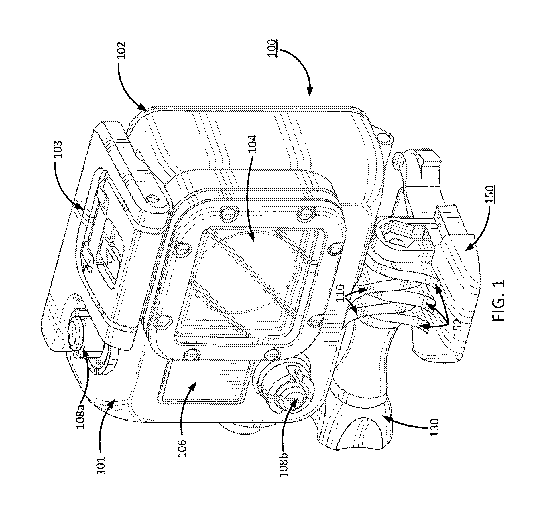
[0013]A camera system can include a camera and a camera housing structured to at least partially enclose the camera. The camera can include a camera body having a camera lens structured on a front surface of the camera body, various indicators on the front of the surface of the camera body (such as LEDs, displays, and the like), various input mechanisms (such as buttons, switches, and touch-screen mechanisms), and electronics (e.g., imaging electronics, power electronics, etc.) internal to the camera body for capturing images via the camera lens and / or performing other functions. The camera housing can include a lens window structured on the front surface of the camera housing and configured to substantially align with the camera lens, and one or more indicator windows structured on the front surface of the camera housing and configured to substantially align with the camera indicators.

[0014]FIG. 1 illustrates a front view of a camera housing 100 and a mount 150,...

example camera helmet

Mount

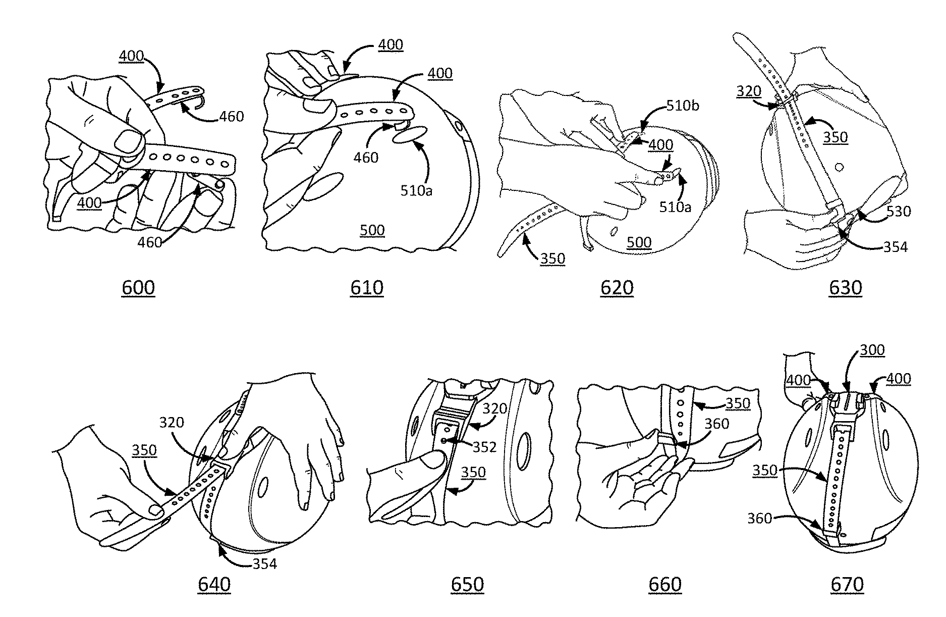
[0029]FIG. 3 illustrates a partially-exploded view of a camera helmet mount, according to one embodiment. FIGS. 4A and 4B further illustrate two perspectives of the assembled camera helmet mount. The camera helmet mount may comprise a main base 300, a rear strap 350, one or more main arms 400, and one or more optional extension arms 450. The rear strap 350 and the main arms 400 may be removably connected to the main base 300. The optional extension arms 450 may also be removably connected to the main arms 400.

[0030]The main base 300 may comprise a mounting portion 310, one or more main arm fasteners 330 (e.g., a first main arm fastener 330a and a second main arm fastener 330b), and a rear strap fastener 320. The mounting portion 310 may secure a camera to the main base 300. In one embodiment, the mounting portion 310 is substantially similar to base 200 described above and couples to mount 150, both described in FIGS. 1-2B. In another embodiment, the mounting portion 310 includ...


PUM


Abstract

A camera helmet mount can removably secure a camera to a helmet via three attachment points, each of which may be a vent hole, a portion of a face mask, or an edge of the helmet. The camera helmet mount may include a main base that couples with a portion of a camera mount, a rear strap, two main arms, and two optional extension arms. The rear strap and two main arms may have hooks at their distal ends opposite the main base that are secured to the three attachment points. The rear strap can be looped through a rear strap fastener of the main base and secured to itself via a strap clip. The main arms may be removably secured to the main base and can be lengthened by installing extension arms and attaching the hooks of the main arms to the other end of the extension arms.

Description

CROSS-REFERENCE TO RELATED APPLICATIONS[0001]This application claims the benefit of U.S. Provisional Patent Application No. 62 / 213,085, filed on Sep. 1, 2015, which is hereby incorporated by reference in its entirety.BACKGROUND1. Technical Field[0002]This disclosure relates to camera mounts, and more specifically, to a camera mount for a helmet.2. Description of the Related Art[0003]A variety of different camera mounts are available for mounting cameras to different types of objects. Mounting a camera to a helmet is desirable to capture action shots in sports such as football, hockey, baseball, or other sports in which athletes typically wear helmets. However, mounting a camera to a helmet may be difficult for a variety of reasons, including a lack of helmet features that may attach to conventional mounts without damaging the helmet. Furthermore, permanently mounting a camera to a helmet may be undesirable because the user may not always want to have the camera installed.SUMMARY[000...

Claims


Application Information

Patent Timeline
IPC IPC(8): G03B17/56A44B13/00A44B17/00A45F5/02F16M13/04
CPCG03B17/561A45F5/02A44B13/00A44B17/0058F16M13/04A42B3/04F16M11/041F16M13/00
Inventor HARRISON, RYANDRUKER, JOSHUA TODD
Owner GOPRO
Why Eureka
Try Eureka