Reactor for use with an ionic liquid catalyst

a technology of ionic liquid catalyst and catalyst, which is applied in the direction of chemical/physical/physical-chemical stationary reactors, chemical apparatus and processes, chemical/physical/physical-chemical processes, etc., can solve the problems of insufficient configuration of such combined units to be effectively and efficiently utilized, inability to control acid concentration, and undesirable control of temperature by vaporization, etc. , to achieve the effect of improving heat transfer efficiency, high velocities and efficient suspension

Active Publication Date: 2017-07-06
UOP LLC
View PDF7 Cites 4 Cited by
  • Summary
  • Abstract
  • Description
  • Claims
  • Application Information

AI Technical Summary

Benefits of technology

[0008]A combined reactor and heat exchanger and a process of using same have been invented. The combined reactor and heat exchanger allows for heat to be removed from the reaction effectively. Additionally, the combined reactor and heat exchanger accommodates the dispersion of the ionic liquid into droplets to catalyze the reaction, while allowing the droplets to be efficiently suspended in the liquid phase. In one particularly preferred aspect, unlike current designs, the process fluid flows through inside the heat exchanger tubes while the cooling fluid flows on the shell side. Additionally, in a particularly preferred design, static mixers may be installed inside the tubes for ionic liquid dispersion and fluid mixing. As the process fluid flows through inside tubes with high velocities (e.g. larger than 10 ft / s) through static mixers, the heat transfer is greatly improved. With static mixers, more uniform droplets of dispersed phase are generated, which makes downstream separation easier.

Problems solved by technology

However, controlling the temperature by vaporization is undesirable because it makes the reactor operation, the ionic liquid dispersion, and the acid concentration more difficult to control.
However, current designs for such combined units are not properly configured to be effectively and efficiently utilized for use with ionic liquid catalyst processes.
The process fluid is on the shell side of the heat exchanger with limited fluid velocities, and thus the heat transfer would be poor for a fluid containing viscous liquid acid catalyst.
In addition, a wide distribution of dispersed-phase liquid droplets and emulsion fluid are created by the high shear pump impellers, which makes downstream separation of the dispersed liquid droplets of ionic liquid catalyst difficult.

Method used


Image

  • Reactor for use with an ionic liquid catalyst
  • Reactor for use with an ionic liquid catalyst
  • Reactor for use with an ionic liquid catalyst

Examples


specific embodiments

[0068]While the following is described in conjunction with specific embodiments, it will be understood that this description is intended to illustrate and not limit the scope of the preceding description and the appended claims.

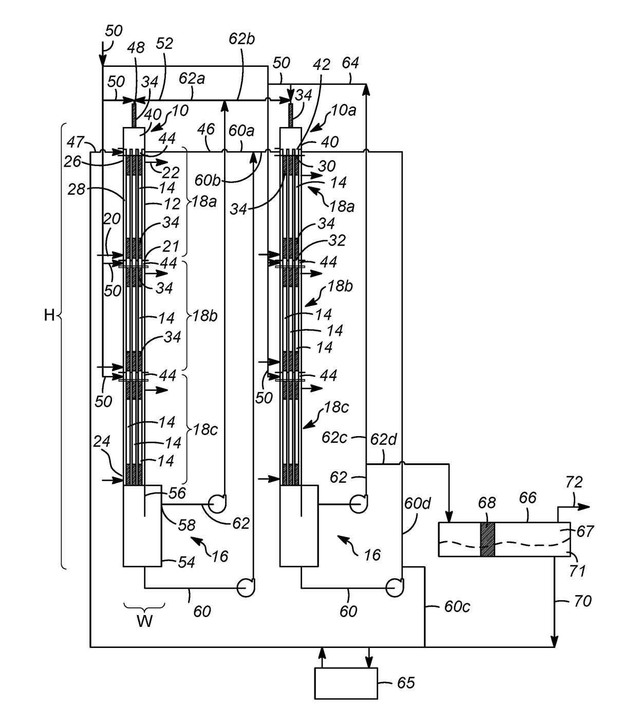
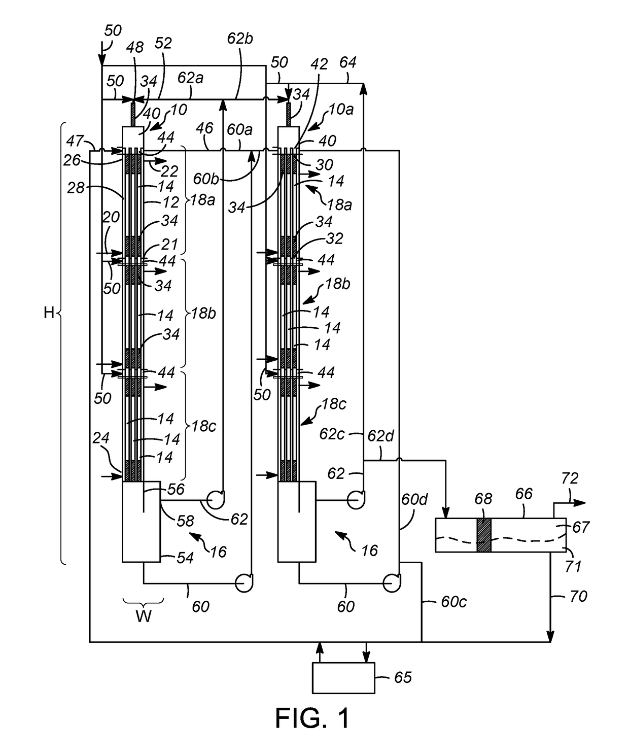
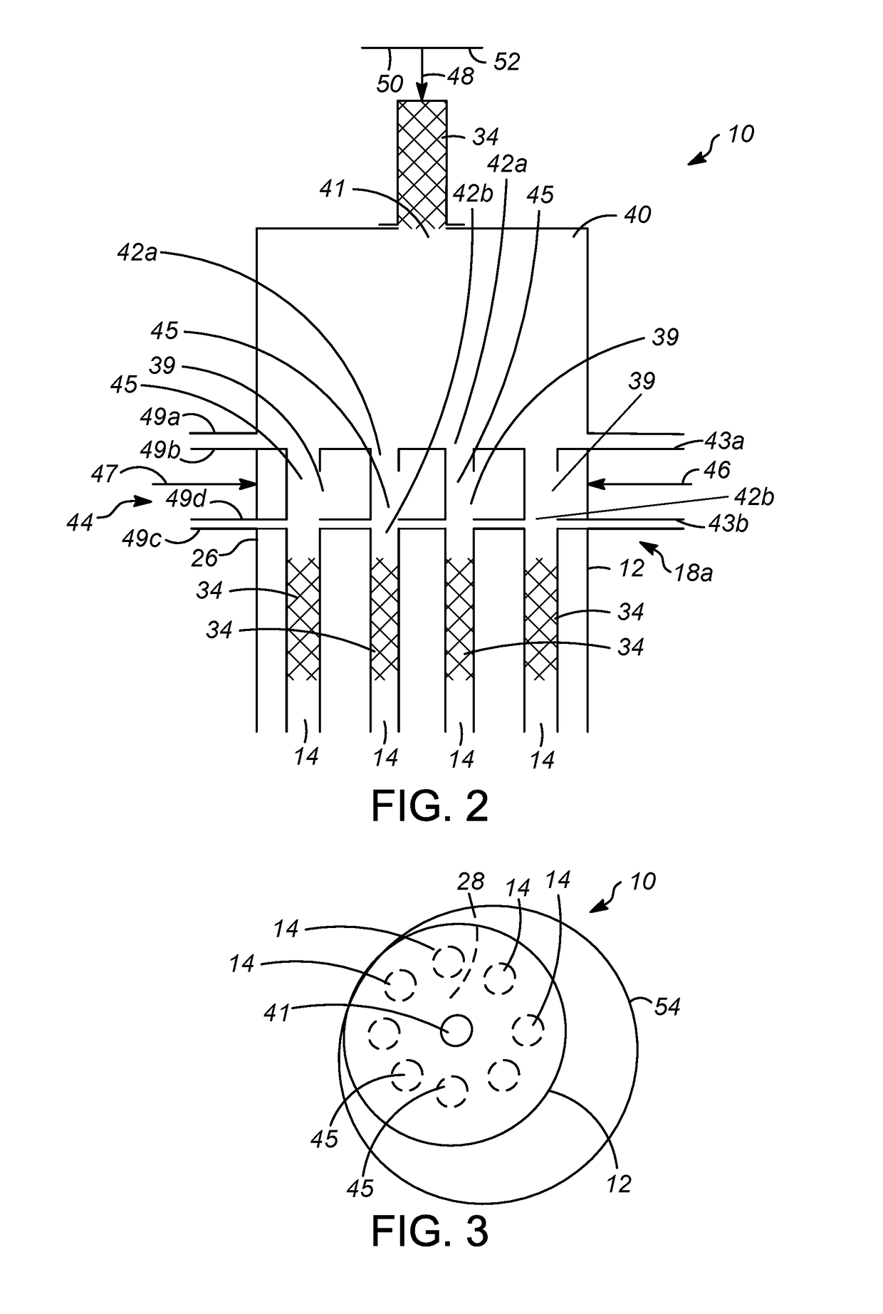
[0069]A first embodiment of the invention is a reactor for an ionic liquid catalyzed reaction, the reactor comprising an outer shell, a hollow member, and a separation zone, the outer shell including an inlet for a cooling fluid and an outlet for the cooling fluid, the hollow member disposed in the outer shell and having a first open end, a second open end opposite the first open end, and at least one static mixer disposed in the hollow member, and, the separation zone in fluid communication with the hollow member and configured to separate an effluent into an ionic liquid stream and a hydrocarbon stream. An embodiment of the invention is one, any or all of prior embodiments in this paragraph up through the first embodiment in this paragraph wherein the react...


PUM


Abstract

A combined heat exchanger and reactor for use with an ionic liquid catalyst reaction. The reactor includes an outer shell configured to receive a cooling fluid which may remove heat from reactions occurring within hollow members disposed inside of the outer shell. The hollow members preferably include one or more static mixers for mixing fluids and dispersing ionic liquid into droplets. A separation zone may be disposed beneath the hollow members which will separate the effluent and provide a hydrocarbon stream and an ionic liquid stream. Multiple combined heat exchanger and reactor may be arranged in series.

Description

CROSS-REFERENCE TO RELATED APPLICATION[0001]This application claims priority from Provisional Application No. 62 / 254,443 filed Nov. 12, 2015, the contents of which are hereby incorporated by reference.FIELD OF THE INVENTION[0002]The invention relates to a reactor for use with ionic liquid catalyst, preferably in an alkylation process, more particularly, the invention relates to a tubular reactor and heat exchanger for use with ionic liquid catalyst.BACKGROUND OF THE INVENTION[0003]Ionic liquids are essentially salts in a liquid state, and are described in U.S. Pat. No. 4,764,440, U.S. Pat. No. 5,104,840, and U.S. Pat. No. 5,824,832. The properties vary extensively for different ionic liquids, and the use of ionic liquids depends on the properties of a given ionic liquid. Depending on the organic cation of the ionic liquid and the anion as well as temperatures, the ionic liquid can have very different properties.[0004]Acidic ionic liquid may be used as a catalyst in various chemical ...

Claims


Application Information

Patent Timeline
Patent Type & Authority Applications(United States)
IPC IPC(8): B01J19/00B01J19/24
CPCB01J19/0013B01J2219/00094B01J2219/24B01J19/2405B01J19/0053B01J19/242B01J19/2425B01J19/2465B01J2219/00047
Inventor XU, ZHANPING
Owner UOP LLC
Why Eureka
Try Eureka