Pants Hanger

a technology for hanging clothes and pants, applied in the field of hanging clothes, can solve the problems of not being able to achieve the foregoing aims of work-dress attire, struggling to feed pants formed of soft, drapeable linens through conventional hangers, and pants becoming unwearable on formal occasions, etc., and achieve the effect of efficient suspension of soft linen fabrics

Inactive Publication Date: 2009-09-10
BONNER JAMES D
View PDF16 Cites 0 Cited by
  • Summary
  • Abstract
  • Description
  • Claims
  • Application Information

AI Technical Summary

Benefits of technology

[0012]It is an object of the present invention to provide an improved clothes hanger that better hangs pants and pants-blouse combinations. It is an object to provide a means to more efficiently suspend soft, linen fabrics that are at a risk of falling off the conventional lower bars they drape. It is an object to provide a means to hang clothing without causing a shift away from the predominant crease on which they are folded. It is an object to provide a hanger that doesn't force pants stretch to manipulate them onto a hanger.
[0013]It is an object that the present invention provides a hanger that reduces the difficult steps required to hang pants on conventional hangers. It is an object to provide a hanger that is simple to manipulate and simple to use.

Problems solved by technology

These hangers are typically found in most closet spaces; however, they don't successfully accomplish the foregoing aims for work-dress attire.
It is often a struggle to feed pants formed of soft, drapeable linens through conventional hangers.
These fabrics wrinkle easily, so inadvertent misalignment can cause the pants to become unwearable on formal occasions.
A further disadvantage is created when slight shifts in pants' weight cause them to slip off of the conventional hanger.
A disadvantage to Schneider is that pants must still be fed through the space formed between the shoulders and the lower bar.

Method used


Image

  • Pants Hanger
  • Pants Hanger
  • Pants Hanger

Examples


Embodiment Construction

[0027]The best mode for carrying out the invention is presented in terms of its preferred embodiment, herein depicted within the Figures.

1. Detailed Description of the Figures

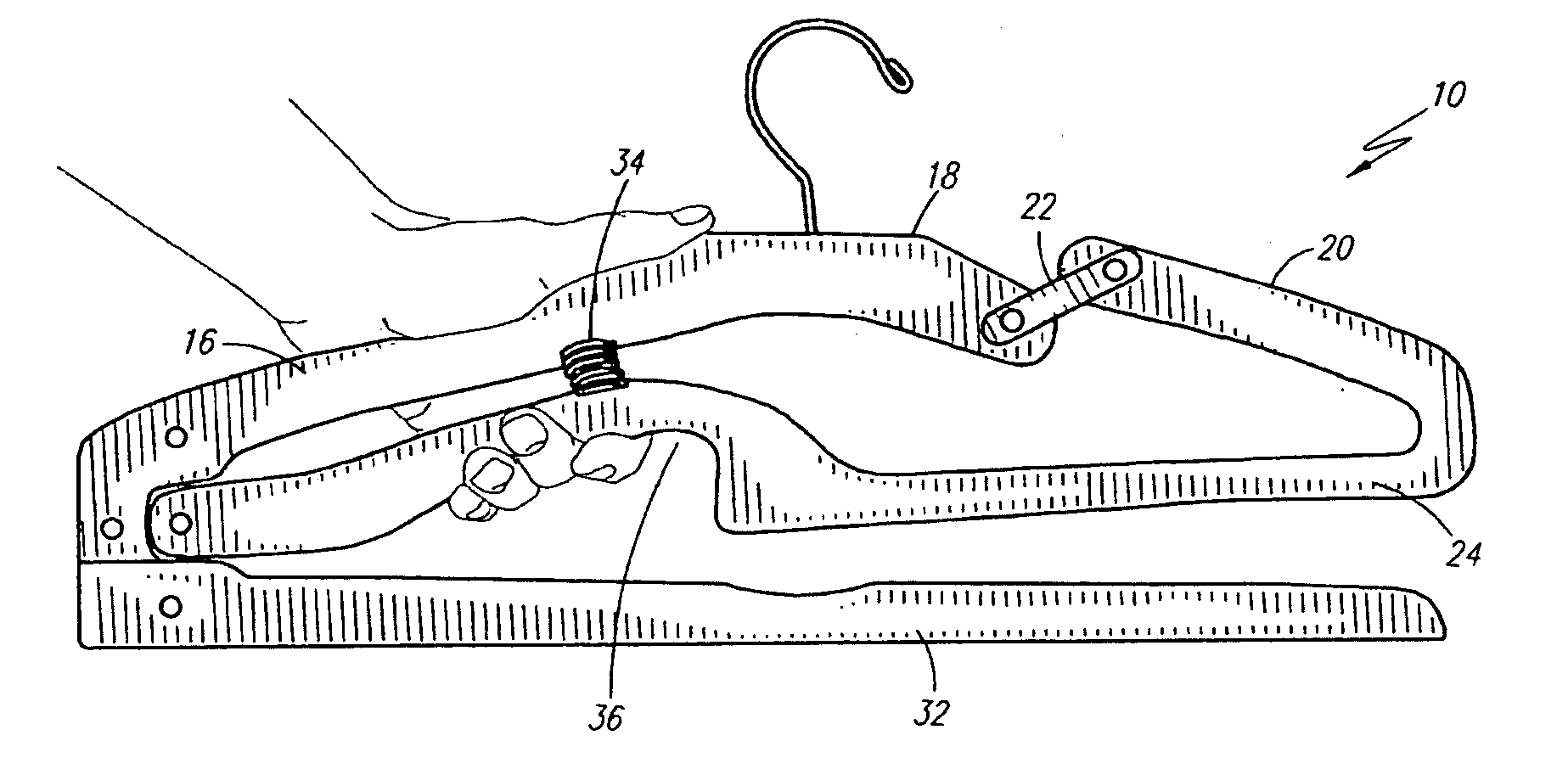
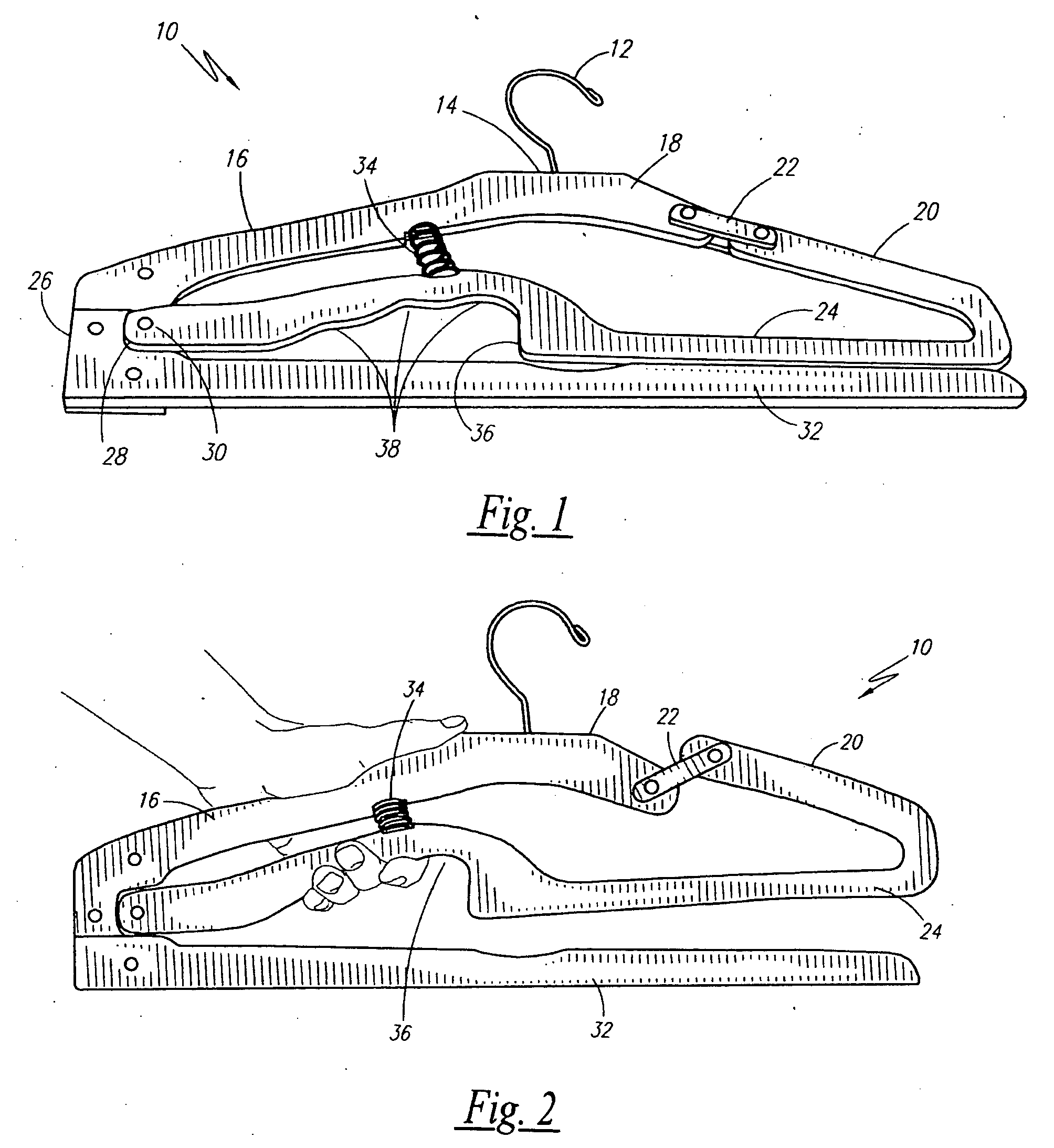
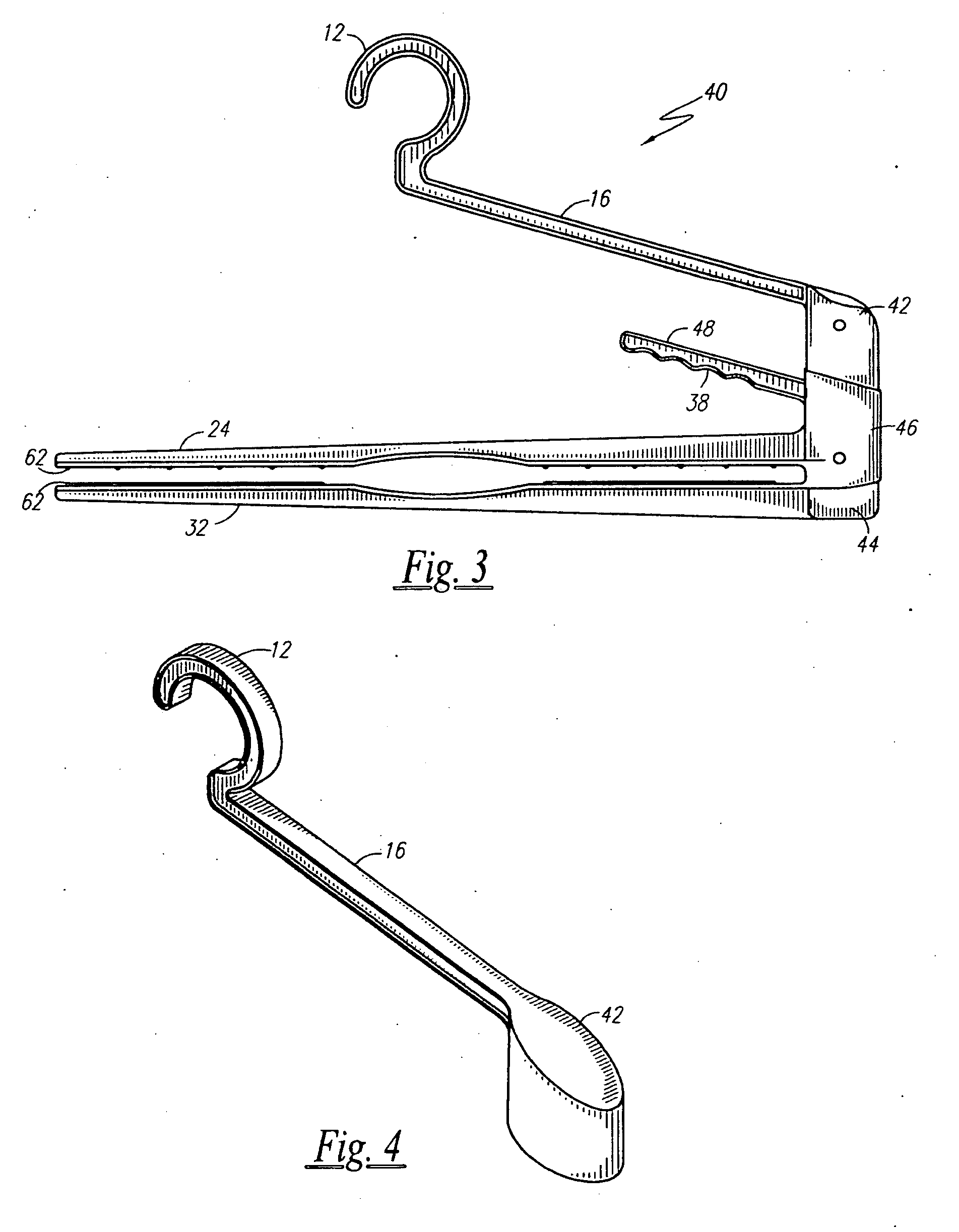
[0028]A preferred embodiment of a pants hanger 10 is shown in FIGS. 1 and 2. A means to suspend 12 the hanger on a closet dowel (not shown) is located at the most upper apex. A hook is the most preferable hanging means 12; however, it is anticipated a nail hook, which mates on a corresponding dowel ring, may also be utilized with the present teachings.

[0029]The hook 12 terminates at a contoured shoulder body 14. The shoulder body 14 includes a first continuous, fixed shoulder portion 16 and an opposite, second and shorter fixed shoulder portion (hereinafter “upper portion 18”) that terminates at approximately ⅓ to ½ of the former's length. A lower, moveable second shoulder portion (hereinafter “lower portion 20”) continues the length of the upper portion 18 so that their combined length mirrors and matches the ...


PUM


Abstract

A hanger includes a standard hook having a contoured shoulder section extending downward therefrom. A first, continuous and fixed shoulder terminates proximate to a flexible lower bar. The second shoulder terminates at a fixed, upper portion, but it remains connected to its lower portion by means of a tension arm therebetween. The lower portion of the second shoulder is continuous with and formed with the flexible lower bar such that a conventional hanger shape is formed. The tension arm, however, provides a means for the lower portion of the second shoulder to push upwards and away from the static portion so that an article of clothing can be secured between the lower bar and a horizontal, static arm that extends below it. A spring formed between the first shoulder and an egress in the lower bar closes the lower bar on the extension arm. The egress is gripped to press the lower bar against the first shoulder, wherein a gripping of the lower bar pushes the bottom portion of the second shoulder upwards so that clearance is formed between the lower bar and the arm so that pants can be slid therebetween.

Description

RELATED APPLICATIONS[0001]The present application is a Continuation of U.S. Ser. No. 61 / 034,682, filed Mar. 7, 2008, and U.S. Ser. No. 61 / 046 / 662, filed Apr. 21, 2008. The present application claims a benefit to the provisional applications' priority dates. The present application furthermore incorporates all of the subject matter of the '682 and the '662 applications as if they are fully rewritten herein.BACKGROUND OF THE INVENTION[0002]1. Field of the Invention[0003]The present invention relates to a clothes hanger and, more specifically, to a hanger that improves hanging of pants or pants-blouse combinations.[0004]2. Description of the Related Art[0005]Pluralities of different designed hangers are placed in wardrobes to suspend various styled articles of clothing. These hangers are designed with a variety of aims: to efficiently suspend clothing; to not wrinkle clothing; to not stretch clothing; and, to conserve space. Conventional wire and plastic hangers comprise inverted v-sha...

Claims


Application Information

Patent Timeline
Patent Type & Authority Applications(United States)
IPC IPC(8): A41D27/22
CPCA47G25/487
Inventor BONNER, JAMES D.
Owner BONNER JAMES D
Why Eureka
Try Eureka