Occupant protection system

a technology for occupant protection and head rest, which is applied in the direction of pedestrian/occupant safety arrangement, vehicular safety arrangment, vehicle components, etc., can solve the problems of difficult to stabilize the deployment behavior of the head rest airbag, and difficult to solve the interference between the upper deploying portion and the head, so as to achieve the stabilization effect of the deployment behavior of the second airbag

Active Publication Date: 2017-07-20
TOYOTA JIDOSHA KK
View PDF3 Cites 19 Cited by
  • Summary
  • Abstract
  • Description
  • Claims
  • Application Information

AI Technical Summary

Benefits of technology

[0031]In this occupant protection system, the upper deploying portion is entirely a cloth that does not have a section that becomes inflated, so even in a case where the distance between the head of the occupant and the roof of the vehicle is short, the deployment behavior of the second airbag can be stabilized.
[0032]As described above, the occupant protection system pertaining to the presen...

Problems solved by technology

H8-175309, it is difficult to stabilize the deployment behavior of the airbag because the airbag becomes inflated and deployed alone from the sides of the head rest.
In the configuration of JP-A No. 2015-13553, the head rest airbag is effective for a relatively small capacity head rest airbag used in combination with a curtain airbag, but it is difficult to stabilize the deployment behavior of the head rest airbag if the capacity of the head rest airbag is increased.
In this occupant protection system, the pair of upper ducts positioned on the upper side of the head of the occupant in the vehicle vertical direction are interposed between both side edge portions of the upper deploying portion and the pair of lateral inflating portions, so it is difficult for interference to arise between the upper deploying portion and the head as the second airbag is being inflated and deployed.
In this occupant protection system, the front side of the second airbag in the vehicle forward and rea...

Method used


Image

  • Occupant protection system
  • Occupant protection system
  • Occupant protection system

Examples


first embodiment

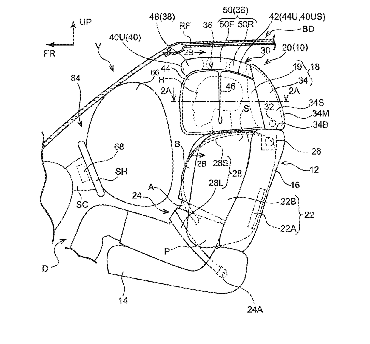
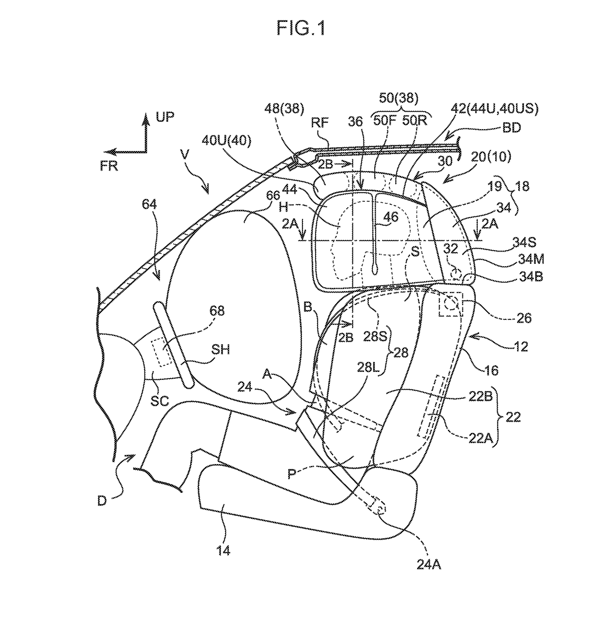
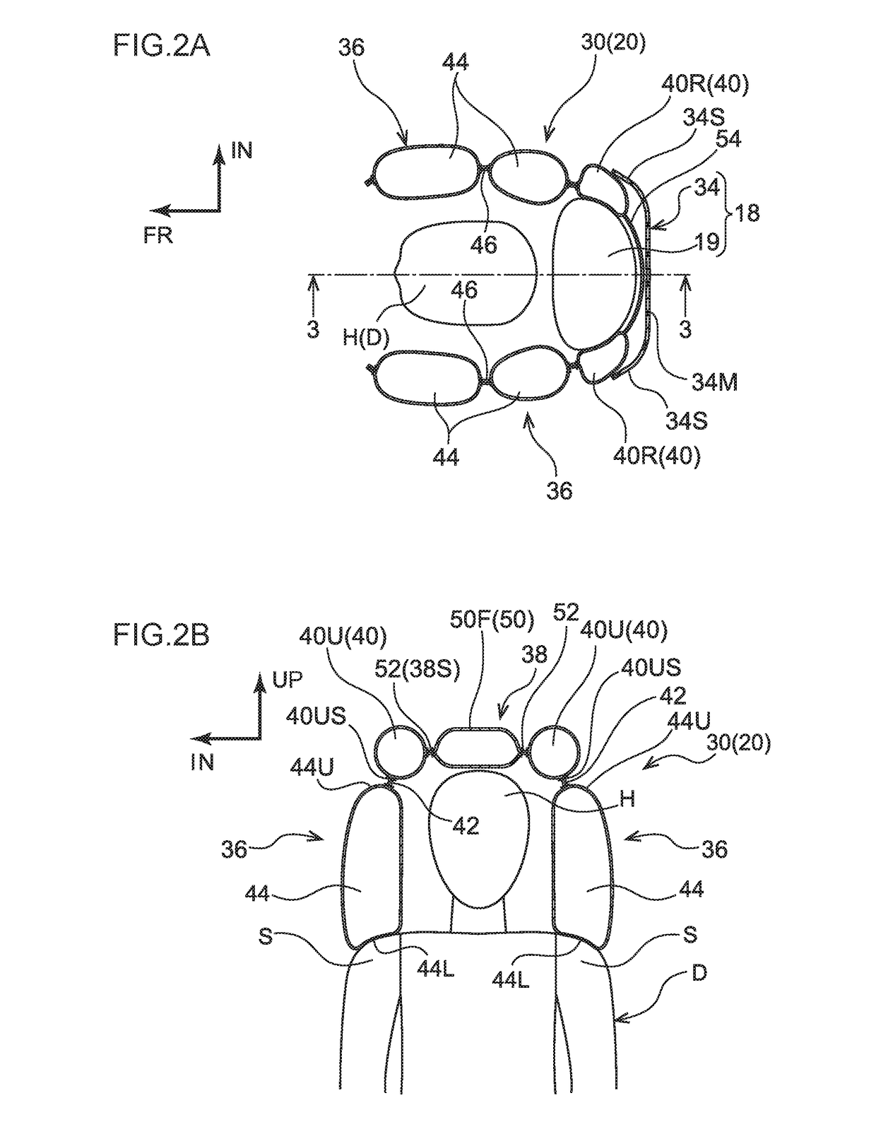
[0056]An occupant protection system 10 pertaining to a first embodiment will now be described on the basis of FIG. 1 to FIG. 7. It should be noted that arrow FR and arrow UP appropriately shown on the drawings indicate a forward direction (the direction that a seated occupant faces) and an upward direction of a vehicle seat 12, respectively. When description is given below simply using the directions of front / rear and upper / lower, unless otherwise specified these will be understood to mean front / rear in the vehicle forward and rearward direction and upper / lower in the vehicle vertical direction. It should also be noted that arrow IN appropriately shown in the drawings indicates a center side in the vehicle width direction of a vehicle V serving as a vehicle in which the vehicle seat 12 is installed.

[0057]{Configuration of Vehicle Seat in which Occupant Protection System is Installed}

[0058]As shown in FIG. 1 to FIG. 4B, the occupant protection system 10 is installed in the vehicle se...

second embodiment

[0144]An occupant protection system 70 pertaining to a second embodiment will be described on the basis of FIG. 10 to FIG. 12. In FIG. 10 the occupant protection system 70 pertaining to the second embodiment is shown by way of a side view corresponding to FIG. 1. Furthermore, in FIG. 11A a sectional view along line 11A-11A of FIG. 10 is shown, and in FIG. 11B a sectional view along line 11B-11B of FIG. 11A is shown. As shown in these drawings, a head protecting airbag device 71 configuring the occupant protection system 70 is equipped with a head protecting airbag 72 instead of the head protecting airbag 30. The head protecting airbag 72 differs from the head protecting airbag 30 in that it includes a front deploying portion 80 that becomes deployed without being inflated in front of the head H and in that the pair of frame ducts 40 have front ducts 40F.

[0145]In the inflated and deployed state of the head protecting airbag 72, the front ducts 40F hang down from the front ends of the...

example modifications

[0152]In the second embodiment, an example was described where the head protecting airbag 72 has the front deploying portion 80, but the present disclosure is not limited to this. For example, as shown in FIG. 13A, FIG. 13B, and FIG. 14, the head protecting airbag 72 may also be given a configuration pertaining to a third example modification that does not have the front deploying portion 80. In the third example modification, the space between the pair of front ducts 40F, that is, the front side of the upper deploying portion 38 in relation to the head H of the driver D, is open. In the configuration pertaining to the third example modification, basically the same effects can be obtained by the same operation as that of the first embodiment.

[0153]Furthermore, in the second embodiment, an example was described where the front deploying portion 80 interconnects, via the front ducts 40F, the pair of lateral inflating portions 44, but the present disclosure is not limited to this. For ...


PUM


Abstract

An occupant protection system including: a first airbag; and a second airbag, wherein the second airbag has a pair of lateral inflating portions which cover the entire head of the occupant from both sides in the vehicle width direction and an upper deploying portion which covers the head of the occupant from the upper side in the vehicle vertical direction, the pair of lateral inflating portions and the upper deploying portion are each supported in back in the vehicle forward and rearward direction by the vehicle seat, and in the inflated and deployed state of the second airbag, vehicle vertical direction upper edge portions of the pair of lateral inflating portions and vehicle width direction side edge portions of the upper deploying portion are connected to each other from their rear end side to their front end side in the vehicle forward and rearward direction.

Description

CROSS-REFERENCE TO RELATED APPLICATION[0001]This application is based on and claims priority under 35 USC 119 from Japanese Patent Application No. 2016-009291 filed on Jan. 20, 2016, the disclosure of which is incorporated by reference herein.BACKGROUND[0002]Technical Field[0003]The present disclosure relates to an occupant protection system.[0004]Related Art[0005]A head rest attached to a seat in a vehicle and equipped with a built-in airbag of an airbag device is known (see Japanese Patent Application Laid-open (JP-A) No. H8-175309). In its inflated state the airbag with which the head rest is equipped expands in a substantially forward direction from the sides of a head portion.[0006]Furthermore, a head rest airbag that is housed in a head rest and configured to receive a supply of gas at the time of a side impact to become inflated and deployed, before a curtain airbag, on both vehicle width direction sides of the head of an occupant is also known (see JP-A No. 2015-13553).[0007...

Claims


Application Information

Patent Timeline
IPC IPC(8): B60R21/233B60R21/215B60R21/237B60R21/26B60R21/203B60R21/207
CPCB60R21/233B60R21/203B60R21/207B60R2021/23308B60R21/26B60R21/215B60R2021/2074B60R21/237B60R21/2035B60R21/2338B60R2021/0048B60R2021/0004B60R2021/0006B60R2021/23146B60R21/231B60R21/261B60R2021/23107B60R2021/2612
Inventor OHNO, MITSUYOSHI
Owner TOYOTA JIDOSHA KK
Why Eureka
Try Eureka