Tip tool holder and power tool

a technology which is applied in the field of power tools and tool holders, can solve the problems that tip tools such as a bit have to be replaced, and achieve the effect of improving the service life of the tool

Inactive Publication Date: 2017-09-14
PANASONIC INTELLECTUAL PROPERTY MANAGEMENT CO LTD
View PDF14 Cites 23 Cited by
  • Summary
  • Abstract
  • Description
  • Claims
  • Application Information

AI Technical Summary

Problems solved by technology

There are cases where a tip tool such as a bit has to be replaced

Method used


Image

  • Tip tool holder and power tool
  • Tip tool holder and power tool
  • Tip tool holder and power tool

Examples


Embodiment Construction

[0022]One aspect of the present invention will now be described by reference to the preferred embodiments. This does not intend to limit the scope of one aspect of the present invention, but to exemplify the teachings.

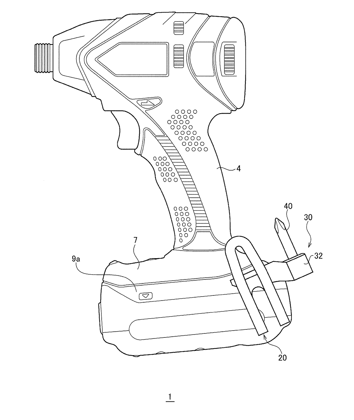
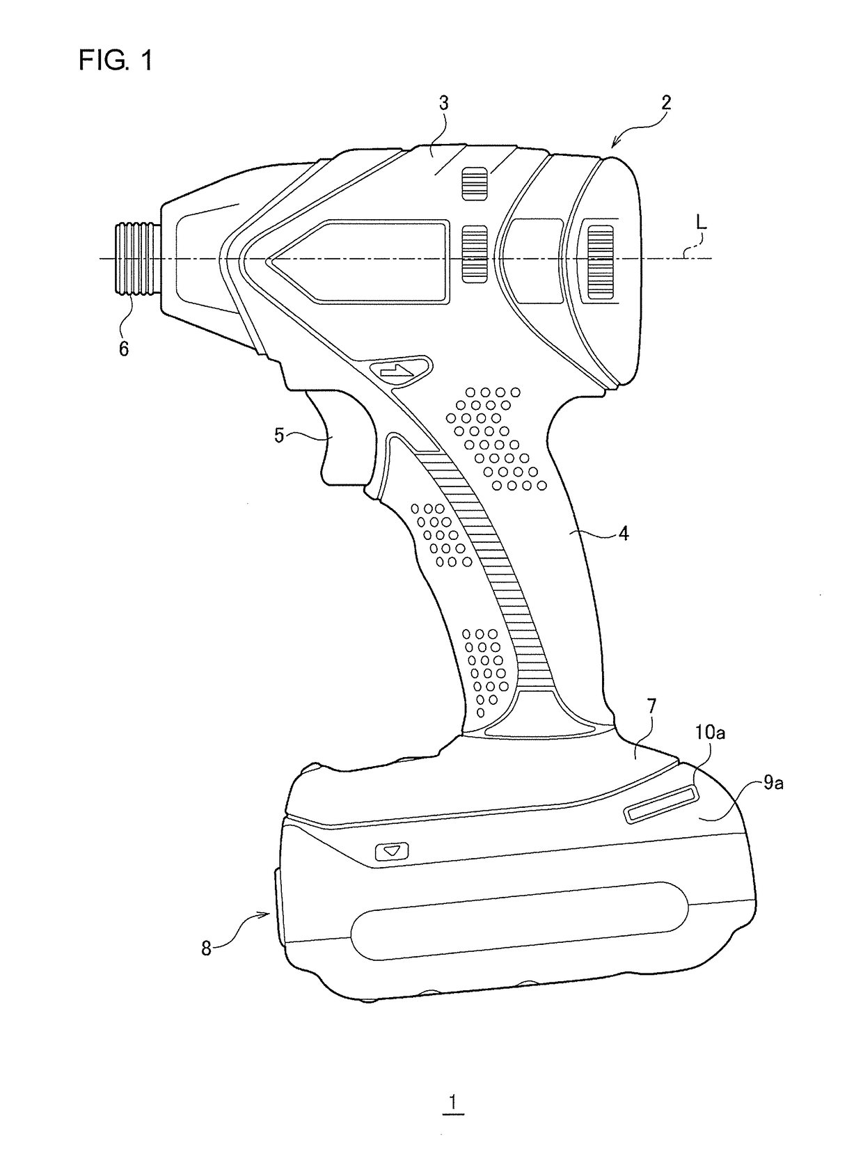
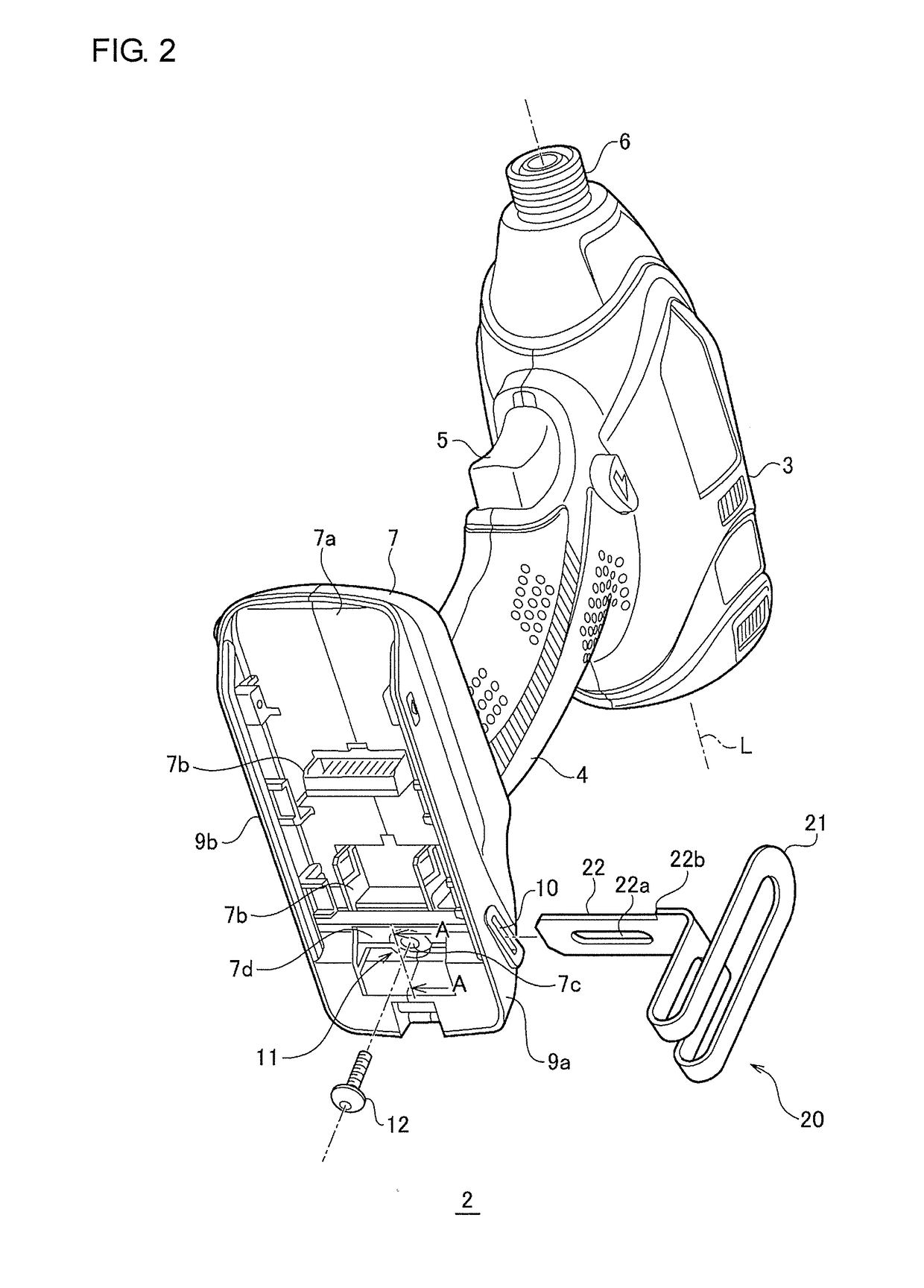
[0023]FIG. 1 is a side view of a power tool 1 of an embodiment. The power tool 1 of the embodiment includes a tool main body 2 and a detachable battery pack 8 incorporating a secondary battery. A housing forming an exterior structure of the tool main body 2 includes a body portion 3 of a cylindrical shape with a bottom, a gripping portion 4 extending downward from the body portion 3, and a base 7 formed under the gripping portion 4. The gripping portion 4 forms a grip for a worker to grasp. A front surface of the gripping portion 4 is formed with an operation switch 5 for a worker to operate. A rear surface of the base 7 is attached with the battery pack 8 formed by a box-shaped case.

[0024]The body portion 3 of the housing accommodates a motor that is a driver, a decel...


PUM


Abstract

A tip tool holder includes a nail portion to be inserted in an attachment hole formed in a power tool, an accommodation portion capable of accommodating a tip tool, and an opening opposite to the nail portion. The accommodation portion accommodates the tip tool such that an axis of the tip tool is substantially perpendicular to a direction in which the nail portion and the opening face each other. The tip tool holder includes a first arm and a second arm opposite to each other. The opening is included in the first arm while the nail portion is provided to the second arm.

Description

CROSS-REFERENCE TO RELATED APPLICATIONS[0001]This application is based upon and claims the benefit of priority of Japanese Patent Application Number 2016-47518, filed on Mar. 10, 2016, the entire contents of which are hereby incorporated by reference.BACKGROUND[0002]1. Field of the Disclosure[0003]The disclosure relates to a structure that holds a tip tool such as a spare bit.[0004]2. Description of the Related Art[0005]There are cases where a tip tool such as a bit has to be replaced due to abrasion or other reasons during work using a power tool. When a plurality of types of work is performed using one power tool, there are cases where the tip tool is replaced depending on the type of work. It is preferable that the power tool holds a spare tip tool for such cases.[0006]For example Japanese Unexamined Patent Application Publication No. 2005-297192 discloses a bit accommodation structure in which a bit accommodation portion that accommodates a bit is included in a recessed manner i...

Claims


Application Information

Patent Timeline
IPC IPC(8): B25F5/02B25H3/00
CPCB25H3/003B25F5/029B25F5/02
Inventor TAKEYAMA, ATUSISAWANO, FUMIAKIKINOSHITA, DAIJU
Owner PANASONIC INTELLECTUAL PROPERTY MANAGEMENT CO LTD
Why Eureka
Try Eureka