Cable connector, carrier module thereof, and method for assembling the same

a technology of cable connectors and carrier modules, applied in the direction of solder/welded conductive connections, coupling device connections, electrical apparatus, etc., can solve the problems of unstable connection between the positioning member and the circuit board, and the inability of the member and the grounding layer to establish a common grounding loop, etc., to achieve the effect of solving the deficiency and shortcoming

Active Publication Date: 2017-10-12
STARCONN ELECTRONICS SU ZHOU CO LTD
View PDF24 Cites 6 Cited by
  • Summary
  • Abstract
  • Description
  • Claims
  • Application Information

AI Technical Summary

Benefits of technology

[0004]The instant disclosure provides a cable connector, a carrier module thereof, and a method for assembling

Problems solved by technology

However, the edge of the positioning member is fixed on the surface of the circuit board by using spot welding, so the connection between the positioning member and the circuit board is unstable.
Moreover, a portion of the positi

Method used


Image

  • Cable connector, carrier module thereof, and method for assembling the same
  • Cable connector, carrier module thereof, and method for assembling the same
  • Cable connector, carrier module thereof, and method for assembling the same

Examples


first embodiment

[0029]Please refer to FIGS. 1 through 11, which show a first embodiment of the instant disclosure. References are hereunder made to the detailed descriptions and appended drawings in connection with the instant invention. However, the appended drawings are merely shown for exemplary purposes, rather than being used to restrict the scope of the instant invention.

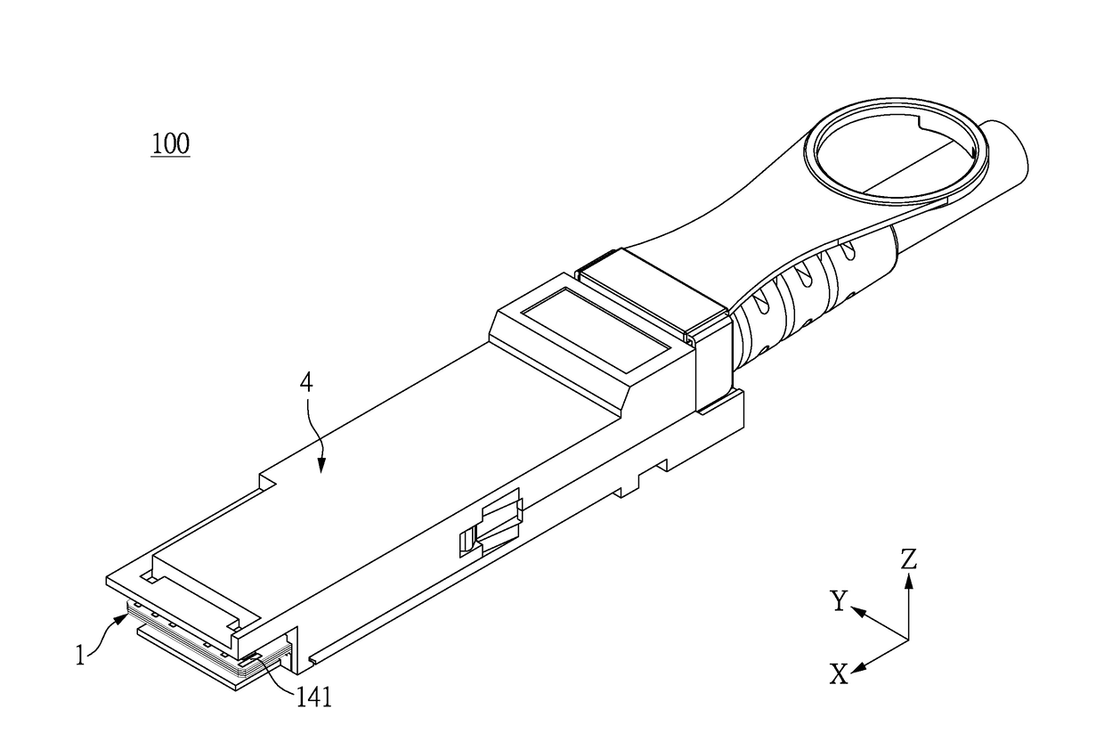
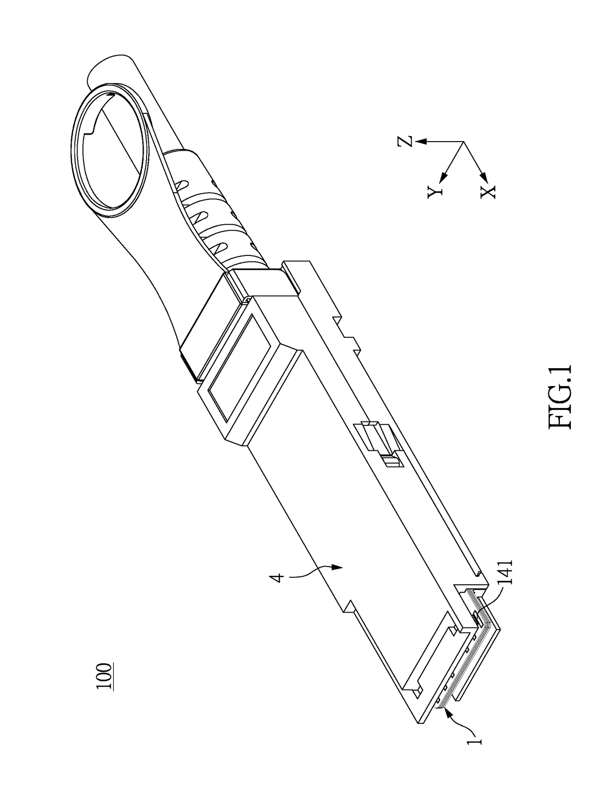
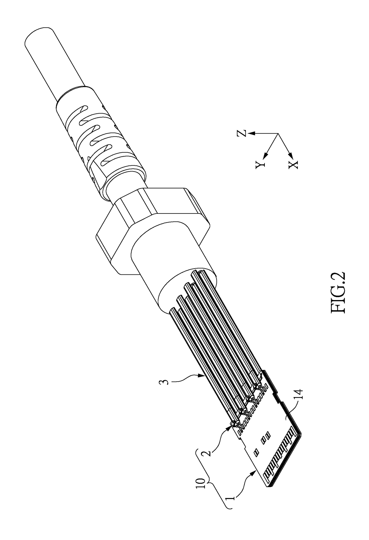
[0030]Please refer to FIGS. 1 through 4, which show a cable connector 100 of the instant embodiment including a circuit board 1, two grounding bars 2, a plurality of conductive cables 3, and a housing 4 receiving the circuit board 1, the grounding bars 2, and part of each conductive cable 3. A front end portion of the circuit board 1 is exposed from the housing 4. The conductive cables 3 are positioned on a rear end portion of the circuit board 1 by using the grounding bars 2.

[0031]FIGS. 2 through 11 do not show the housing 4 in order to more clearly show the inner construction of the cable connector 100, and each figure show...

second embodiment

[0056]Please refer to FIGS. 12 and 13, which show a second embodiment. The second embodiment is similar to the first embodiment, the different features between the two embodiments being the construction of the grounding bar 2 and the corresponding portion of the circuit board 1.

[0057]The base portion 21 of the grounding bar 2 in the instant embodiment is an elongated structure, in other words, the base portion 21 in the instant embodiment is substantially identical to the beam 211 disclosed in the first embodiment. The conductive portions 22 of the grounding bar 2 are curvedly extended from a long edge of the base portion 21. The conductive cables 3 are disposed on the circuit board 1, and then the conductive portions 22 of the grounding bar 2 are respectively inserted into the holes 16′ of the circuit board 1, so the metallic shielding layers 33 of the conductive cables 3 are clamped between the base portion 21 and the circuit board 1, thereby firmly fixing the conductive cables 3 ...

third embodiment

[0058]Please refer to FIGS. 14 and 15, which show a third embodiment. The third embodiment is similar to the first embodiment, the different features between the two embodiments being the construction of the grounding bar 2 and the corresponding portion of the circuit board 1.

[0059]Two holes 16′ in the instant embodiment are formed on two opposite sides of the circuit board 1 (i.e., the left side and the right side of the circuit board 1 shown in FIG. 15) and penetrate the first surface 14 and the second surface 15. The circuit board 1 includes two conductive extensions 18′ respectively coated on the inner walls, which define the holes 16′. The grounding bar 2 includes two elastically conductive portions 22 respectively and curvedly extended from two opposite ends of the beam 211. The two conductive portions 22 are inserted into the holes 16′ and clamp the conductive extensions 18′ arranged in the holes 16′.


PUM


Abstract

A carrier module of a cable connector includes a circuit board and a grounding bar disposed on the circuit board. The circuit board includes a first insulating layer, a second insulating layer, and a grounding layer arranged between the first and second insulating layers. The circuit board has a hole formed on a surface thereof and a conductive extension disposed within the hole, and the conductive extension is connected to the grounding layer. The grounding bar includes a base portion and a conductive portion connected to the base portion. The conductive portion is inserted into the hole, and connected to the conductive extension, thereby electrically connecting the grounding bar and the grounding layer of the circuit board. Thus, the carrier module of the instant disclosure is provided with the grounding bar having well grounding performance which is firmly fixed on the circuit board.

Description

BACKGROUND OF THE INVENTION1. Field of the Invention[0001]The instant invention relates to a connector, in particular, to a cable connector, a carrier module thereof, and a method for assembling the cable connector.2. Description of Related Art[0002]The conventional cable connector includes a circuit board, a plurality of cables, and a positioning member. One end of each cable is welded on a surface of the circuit board, and an edge of the positioning member is welded on the surface of the circuit board to press the cables, such that the cables are clamped by the circuit board and the positioning member.[0003]However, the edge of the positioning member is fixed on the surface of the circuit board by using spot welding, so the connection between the positioning member and the circuit board is unstable. Accordingly, when any cable and the circuit board are pulled to generate a shearing force, the positioning member is easily separated from the surface of the circuit board because of t...

Claims


Application Information

Patent Timeline
IPC IPC(8): H01R4/02H01R12/72
CPCH01R12/721H01R4/023H01R12/53H01R12/585H01R13/6595H01R13/65914
Inventor PAO, CHUNG-NANLIN, YU-HSIUNGLAI, YI-GUANGHSU, MING-CHUNWU, KAI
Owner STARCONN ELECTRONICS SU ZHOU CO LTD
Why Eureka
Try Eureka