
System and method for beam management

a beam management and beam technology, applied in the field of communication systems, can solve the problem of relatively high path loss in millimeter wave (mmw) systems, and achieve the effect of reducing path loss and relatively low path loss

Active Publication Date: 2017-10-19
QUALCOMM INC
View PDF1 Cites 107 Cited by
  • Summary
  • Abstract
  • Description
  • Claims
  • Application Information

AI Technical Summary

Benefits of technology

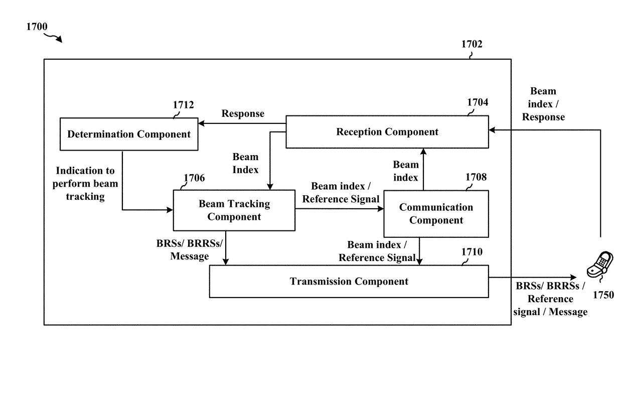
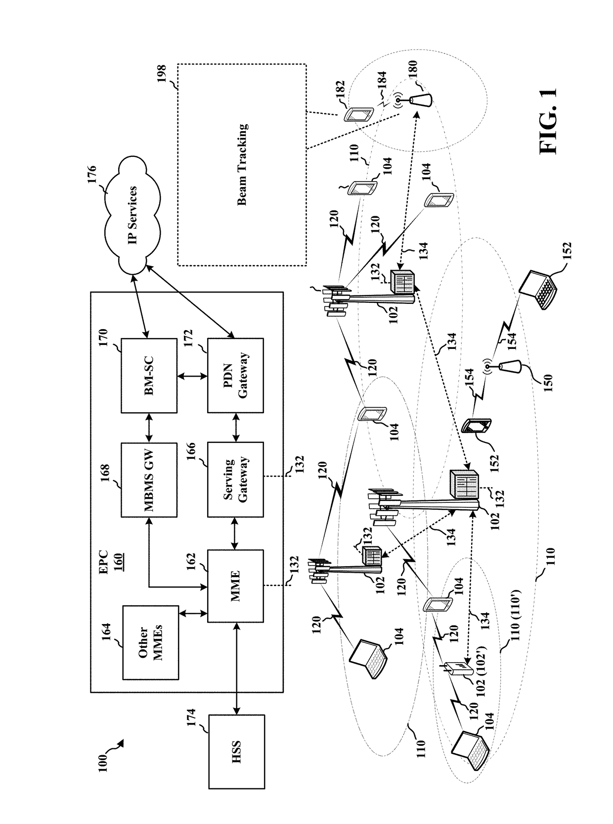
The patent text discusses a way to improve communication in millimeter wave systems by using ready-to-use beams. The problem with millimeter wave systems is that they have high path loss, which means signals can easily be lost during transmission. To address this, the base station sends out beam reference signals in all directions, allowing the user equipment to identify the best "coarse" beam for communication. If the "coarse" beam changes, the user equipment needs to inform the base station so that the base station can train new "fine" beams for the user equipment. This process helps to improve the reliability of communication in millimeter wave systems.

Problems solved by technology

Path loss may be relatively high in millimeter wave (mmW) systems.

Method used


Image

  • System and method for beam management
  • System and method for beam management
  • System and method for beam management

Examples


Embodiment Construction

[0040]The detailed description set forth below in connection with the appended drawings is intended as a description of various configurations and is not intended to represent the only configurations in which the concepts described herein may be practiced. The detailed description includes specific details for the purpose of providing a thorough understanding of various concepts. However, it will be apparent to those skilled in the art that these concepts may be practiced without these specific details. In some instances, well known structures and components are shown in block diagram form in order to avoid obscuring such concepts.

[0041]Several aspects of telecommunication systems will now be presented with reference to various apparatus and methods. These apparatus and methods will be described in the following detailed description and illustrated in the accompanying drawings by various blocks, components, circuits, processes, algorithms, etc. (collectively referred to as “elements...


PUM


Abstract

A first apparatus may communicate with a user equipment through a first active beam. The first apparatus may determine that beam tracking is to be performed with the UE, including identifying a new beam for communication between the UE and the apparatus. The first apparatus may perform beam tracking with the UE based on the determination that beam tracking is to be performed. The first apparatus may communicate with the UE through a second active beam based on the beam tracking.

Description

CROSS-REFERENCE TO RELATED APPLICATION(S)[0001]This application claims the benefit of U.S. Provisional Application Ser. No. 62 / 322,168, entitled “TRANSMIT REQUEST FOR BEAM TRACKING” and filed on Apr. 13, 2016, U.S. Provisional Application Ser. No. 62 / 329,180, entitled “TRANSMIT REQUEST FOR BEAM TRACKING” and filed on Apr. 28, 2016, U.S. Provisional Application Ser. No. 62 / 333,120, entitled “TRANSMIT REQUEST FOR BEAM TRACKING” and filed on May 6, 2016, U.S. Provisional Application Ser. No. 62 / 337,829, entitled “TRANSMIT REQUEST FOR BEAM TRACKING” and filed on May 17, 2016, U.S. Provisional Application Ser. No. 62 / 338,484, entitled “TRANSMIT REQUEST FOR BEAM TRACKING” and filed on May 18, 2016, U.S. Provisional Application Ser. No. 62 / 341,051, entitled “TRANSMIT REQUEST FOR BEAM TRACKING” and filed on May 24, 2016 and U.S. Provisional Application Ser. No. 62 / 447,386, entitled “SYSTEM AND METHOD FOR BEAM INDEX and filed on Jan. 17, 2017. The disclosures of the aforementioned provisiona...

Claims


Application Information

Patent Timeline
Patent Type & Authority Applications(United States)
IPC IPC(8): H04B7/06H04L5/00
CPCH04B7/0639H04L5/0051H04B7/0695H04L5/0048H04W72/046H04L5/0053H04L5/0057H04B7/0417H04B7/0617H04B7/0621H04B7/088H04W72/21H04W72/23H04W74/0833
Inventor ISLAM, MUHAMMAD NAZMULLUO, TAOCEZANNE, JUERGENSUBRAMANIAN, SUNDARSAMPATH, ASHWINSADIQ, BILALLI, JUNYI
Owner QUALCOMM INC
Learn More