Spring assist cable clamps

a cable clamp and spring technology, applied in the field of clamps, can solve the problems of not being able to support a ladder leaning against, bolted cable clamps are not suitable for self-supporting fiber optic cables, and needing drop connections,

Active Publication Date: 2018-02-01
HUBBELL INC
View PDF8 Cites 16 Cited by
  • Summary
  • Abstract
  • Description
  • Claims
  • Application Information

AI Technical Summary

Benefits of technology

[0007]The present disclosure provides embodiments of cable clamps for clamping drop cables to main span cables. In one exemplary embodiment, the cable clamp has a body, a stem and a spring. The body has an elongated drop cable guide, an elongated main span cable guide and a main body section between the drop cable guide and the main span cable guide. The body has a lower body half coupled to an upper body half using the stem and spring, where the lower body half is movable relative to the upper body half between one or more open position and a clamping position. When the body is in the clamping position, the lower body half and upper body half of the drop cable guide form a drop cable opening and the lower body half and upper body half of the main span cable guide form a main span cable opening. The stem extends through the lower body half of the main body section and is releasably secured to the upper body half of the main body section such that rotational movement of the stem is translated t

Problems solved by technology

However, there are instances where drop connections are needed.
However, such bolted cable clamps are not suitable for self-supporting fiber optic cable as they do not use a galvanized steel support wire.
In addition, self-supporting fiber optic cables do not allow for the suppo

Method used


Image

  • Spring assist cable clamps
  • Spring assist cable clamps
  • Spring assist cable clamps

Examples


Embodiment Construction

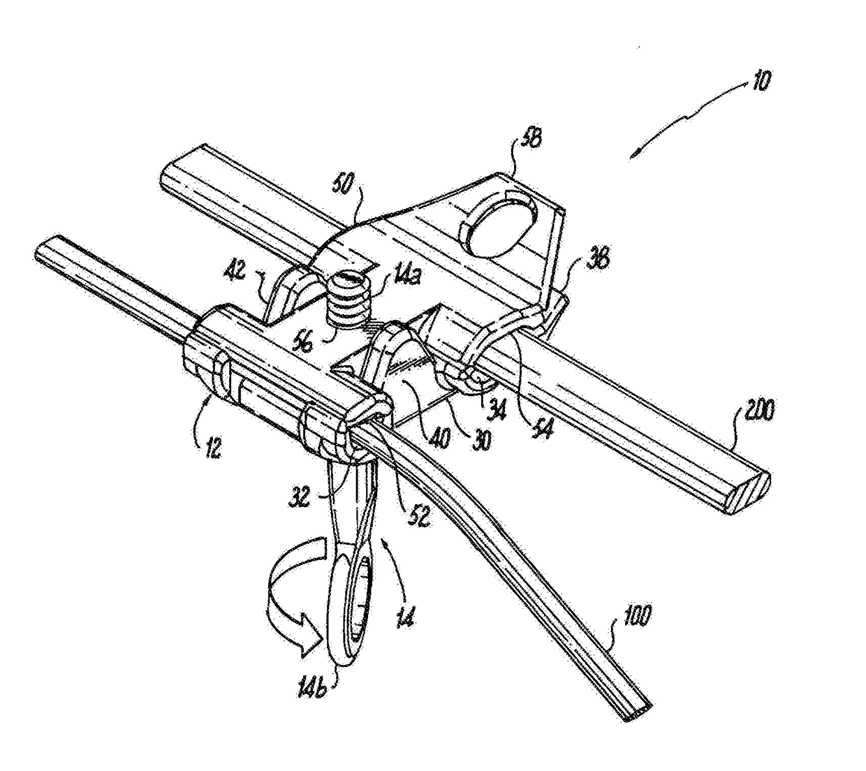
[0058]Exemplary embodiments of the cable clamp of the present disclosure are shown. For ease of description, the cable clamp described herein may also be referenced as the “clamp.” The clamp according to the present disclosure is configured to be installed from the ground with an extendable reach tool, such as a hot stick. Initial spring tension temporarily holds a drop cable in a drop cable opening in a drop cable section of the clamp, and a main span cable is snapped into a main span cable opening in a main span cable section of the clamp.

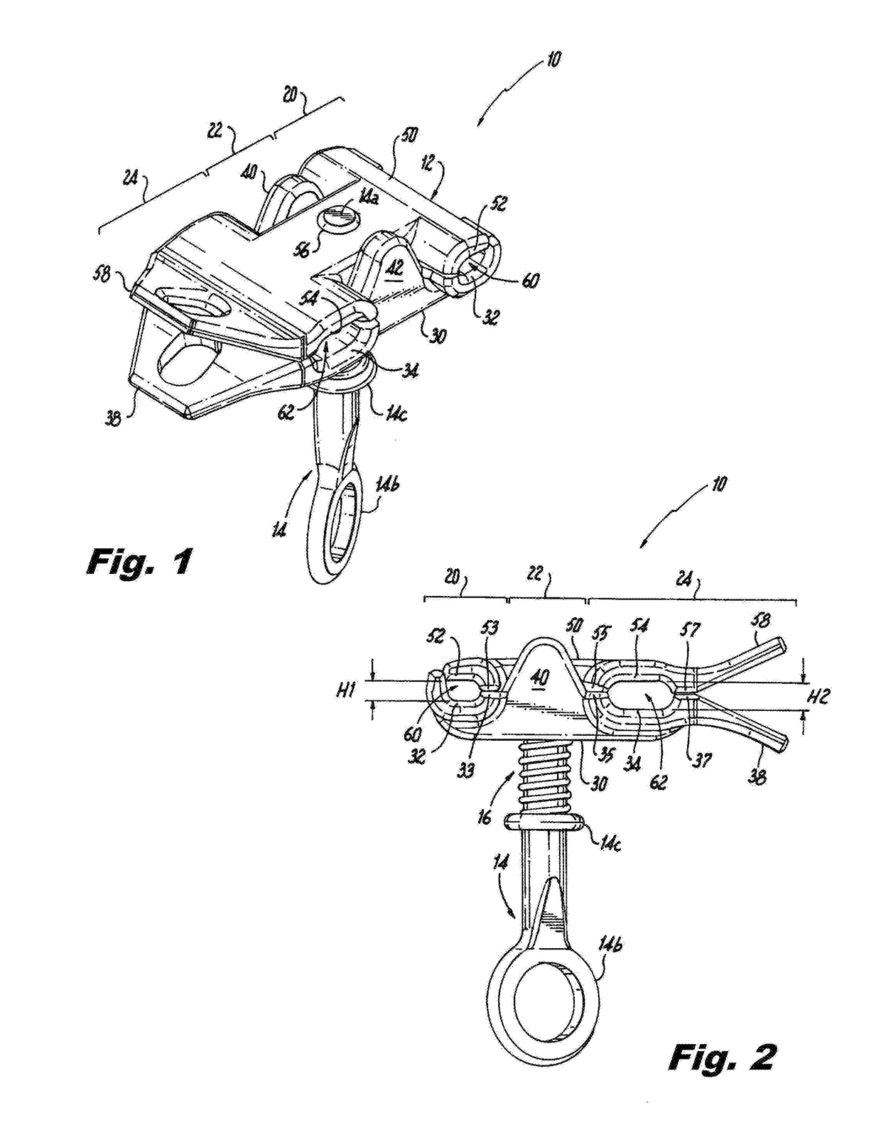
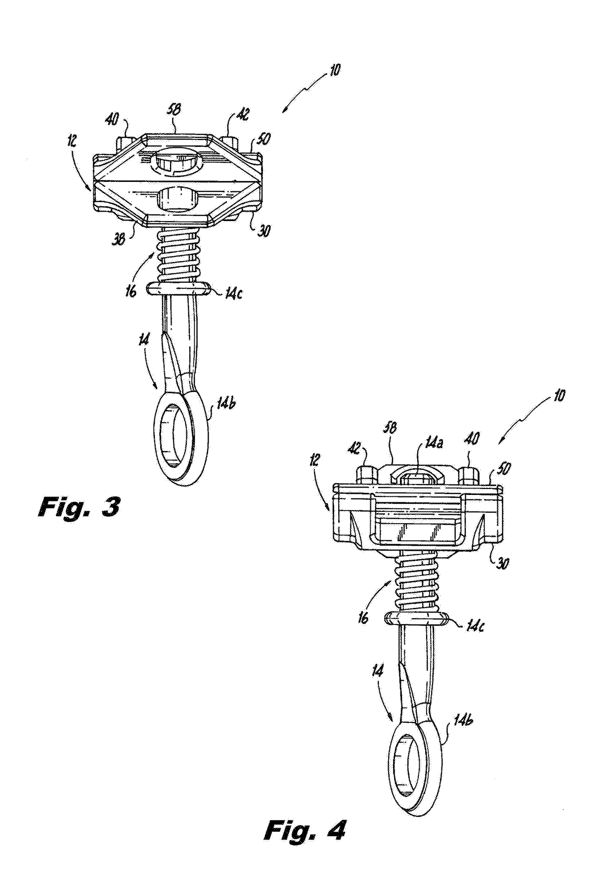
[0059]Referring now to the figures, in particular FIGS. 1-6, an exemplary embodiment of the clamp according to the present disclosure is shown. The clamp 10 includes a body 12, a stem 14 and a spring 16. The body 12 has a lower body half 30 and an upper body half 50. For general reference purposes the body 12 is split into three sections: a drop cable section 20, an intermediate section 22 and a main span cable section 24. The stem 14 is preferab...


PUM


Abstract

A cable clamp for clamping drop cables to main span cables. The cable clamp has a body that includes an elongated drop cable guide, an elongated main span cable guide, and main body section between the drop cable guide and the main span cable guide. The body has a lower body half and an upper body half. The lower body half is movable relative to the upper body half between at least one open position and a clamping position. When the body is in a clamping position the lower body half and upper body half of the drop cable guide form a drop cable opening, and the lower body half and upper body half of the main span cable guide form a main span cable opening. A stem extends through the lower body half of the main body section and is releasably secured to the upper body half of the main body section such that rotational movement of the stem is translated to movement of the lower body half relative to the upper body half. The stem has a collar and a spring is positioned on the stem between the collar and the lower body half of the main body section to normally bias the body to the clamping position.

Description

CROSS REFERENCE TO RELATED APPLICATIONS[0001]The present application is based on and claims benefit from co-pending U.S. Provisional Application Ser. No. 62 / 368,462 filed Jul. 29, 2016 entitled “Spring Assist Cable Clamps” and from co-pending U.S. Provisional Application Ser. No. 62 / 509,240 filed May 22, 2017 entitled “Spring Assist Cable Clamps” and the entire contents of both are incorporated herein by reference.BACKGROUNDField[0002]The present disclosure relates generally to clamps for utility cabling and more particularly to cable clamps for clamping drop cables to main span cables.Description of the Related Art[0003]Aerial cabling, such as fiber optic cabling, is typically strung from utility pole to utility pole, or from a utility pole to a building. The cabling between utility poles is often referred to as a main span. To withstand cable sag and environmental conditions, two types of fiber optic cables are available to string from pole-to-pole or from pole-to-building: lashed...

Claims


Application Information

Patent Timeline
IPC IPC(8): G02B6/44H02G7/08F16L3/10
CPCG02B6/4471G02B6/4478H02G7/08F16L3/1033G02B6/483H01R11/15Y10T24/3439H01R4/44
Inventor AL GHOSSEIN, RABIH M.SAKMAR, JOHN EDWARD
Owner HUBBELL INC
Why Eureka
Try Eureka