Locking system having an electronic deadbolt

a technology of electronic deadbolt and locking system, which is applied in the direction of non-mechanical control, construction fastening device, mechanical energy handling, etc., can solve the problems of difficult to determine whether the door is actually locked, and the door to be breached

Active Publication Date: 2018-02-22
AMESBURY GROUP
View PDF12 Cites 22 Cited by
  • Summary
  • Abstract
  • Description
  • Claims
  • Application Information

AI Technical Summary

Problems solved by technology

Motorized deadbolts are also available, but these can display disadvantages.
For example, it can often be difficult to determine whether the door is actually locked without attempting to open the door.
This can cause the door to be breached if the user believes it to be locked when that is, in fact, not so.

Method used


Image

  • Locking system having an electronic deadbolt
  • Locking system having an electronic deadbolt
  • Locking system having an electronic deadbolt

Examples


Embodiment Construction

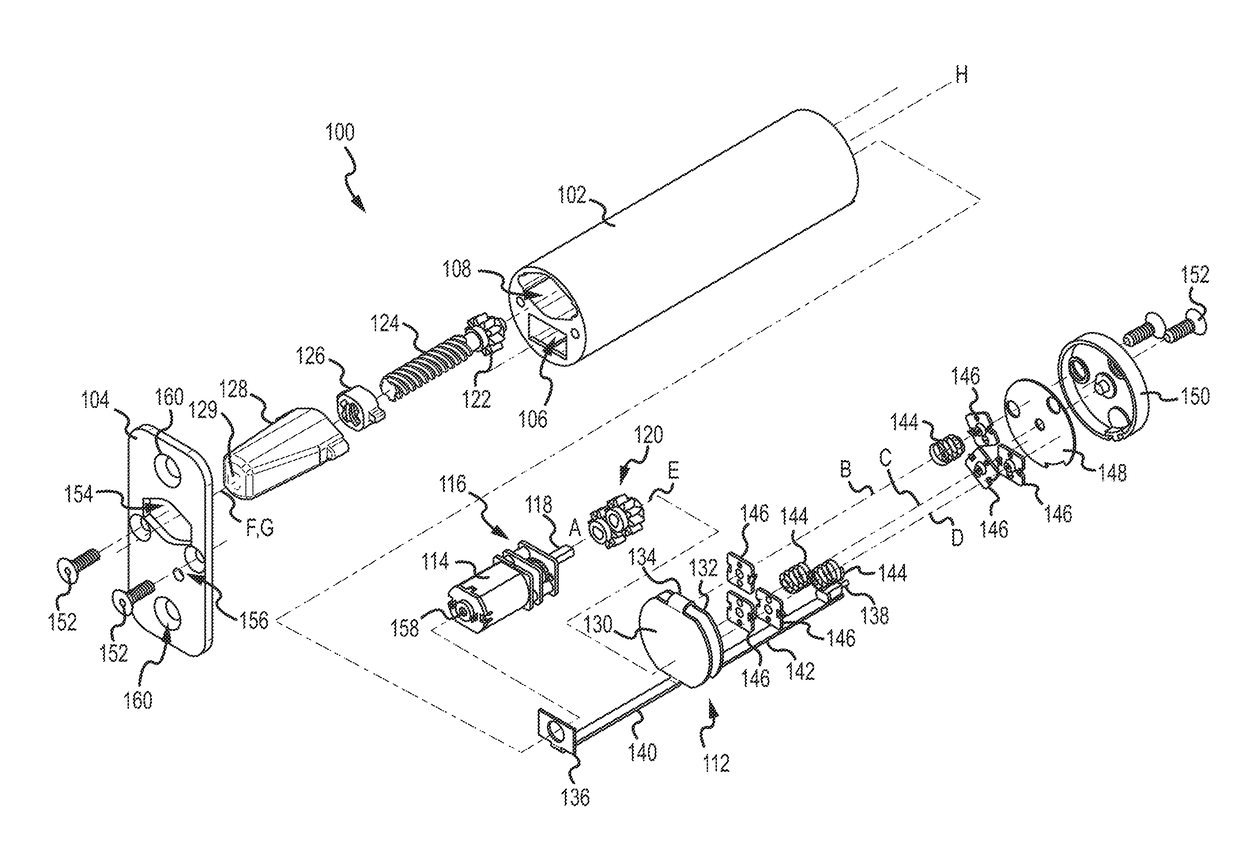
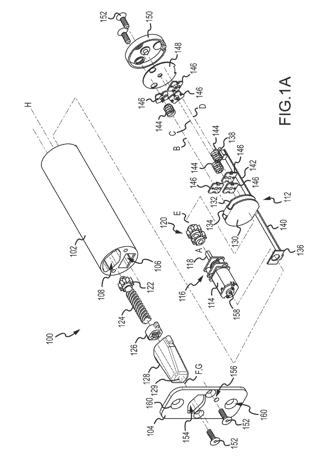
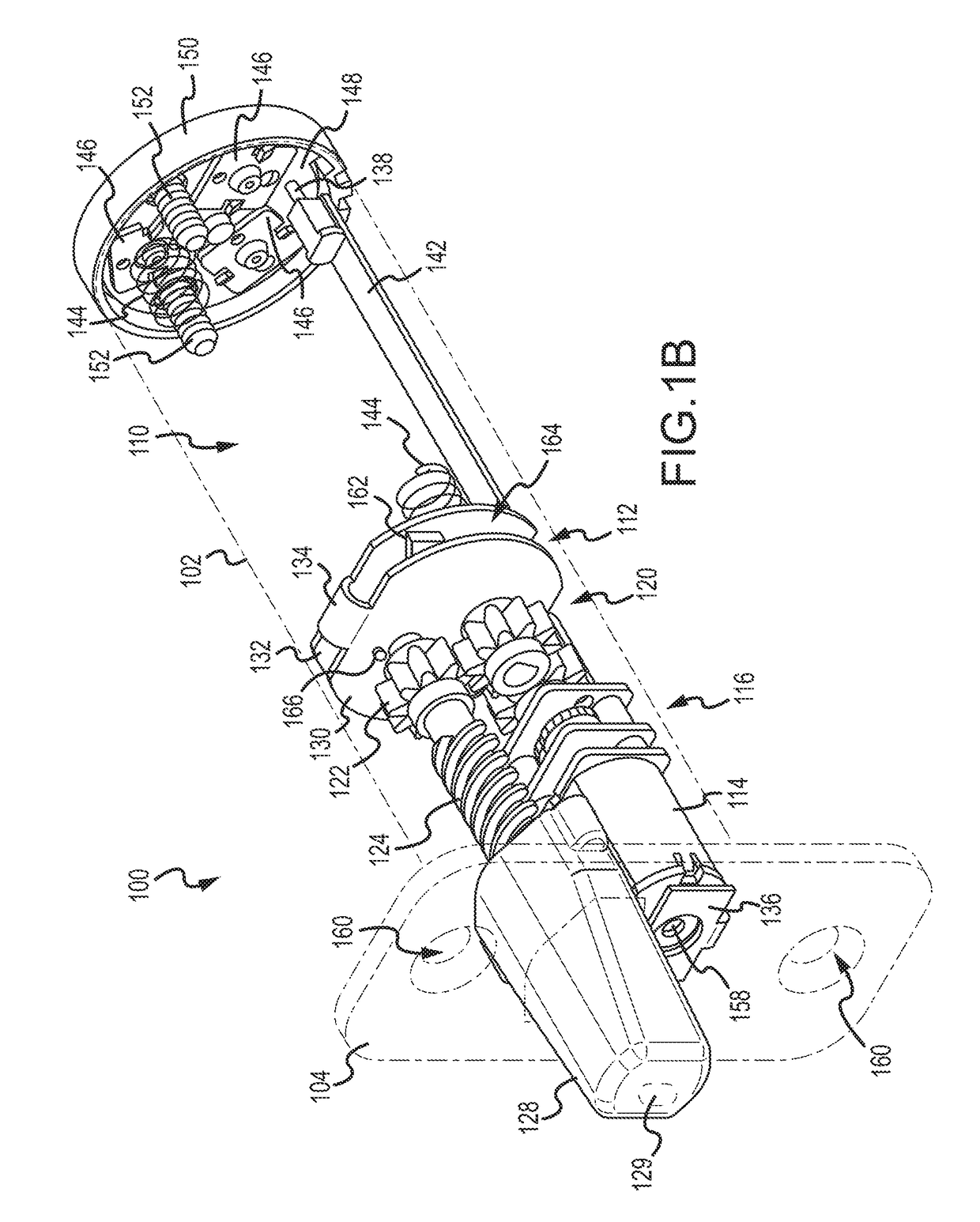
[0020]FIGS. 1A and 1B are exploded perspective and partial perspective views, respectively, of an electronic deadbolt system 100 and are described concurrently. In FIG. 1B, certain components, e.g., a housing 102 and a face plate 104, are depicted in dashed lines to depict more clearly the assembled components contained within the deadbolt system 100. The housing 102 defines a motor chamber 106, a deadbolt chamber 108, and a battery chamber 110. The motor chamber 106 and the deadbolt chamber 108 may be combined into a single chamber, if required or desired. Internal structures within the housing 102 that separate the motor chamber 106 from the deadbolt chamber 108 are not depicted in FIG. 1B. The motor chamber 106 and the deadbolt chamber 108 are separated from the battery chamber 110 by portions of a circuit board 112, as described in more detail below. The motor chamber 106 is configured to receive a motor 114 that includes a motor shaft having an axis that is coaxial with drive s...


PUM


Abstract

A motor with a shaft and a shaft axis is disposed within a housing. A lead screw has an axis and is rotatably mounted in the housing. A deadbolt linearly extends from the housing based on rotation of the lead screw. A gear set with a plurality of gears, each having an axis, is disposed in the housing and operably connects the motor and the lead screw. A circuit board is disposed within the housing and has a plurality of portions communicatively connected by a ribbon. Each portion is disposed substantially orthogonal to the motor shaft axis, the lead screw axis, and the plurality of gear axes.

Description

INTRODUCTION[0001]Deadbolts are operated by a user (e.g., with a key on an outside of the door or a thumbturn on the inside of the door) to secure the door against unwanted intrusions. Motorized deadbolts are also available, but these can display disadvantages. For example, it can often be difficult to determine whether the door is actually locked without attempting to open the door. This can cause the door to be breached if the user believes it to be locked when that is, in fact, not so.SUMMARY[0002]In one aspect, the technology relates to an apparatus having: a housing; a motor having a motor shaft having a motor shaft axis, wherein the motor is disposed in the housing; a lead screw having a lead screw axis, wherein the lead screw is rotatably mounted in the housing; a deadbolt configured to be linearly extended from the housing based on a rotation of the lead screw; a gear set having a plurality of gears, wherein each of the plurality of gears includes a gear axis, and wherein th...

Claims


Application Information

Patent Timeline
Patent Type & Authority Applications(United States)
IPC IPC(8): E05B47/00H02K7/116H02K7/06E05B15/10E05B9/00E05B15/02E05B17/00E05B9/02E05C9/00
CPCE05B47/0012E05B2047/0058H02K7/06E05B15/10E05B9/002E05B15/0205E05B17/0004E05B9/02E05C9/00E05B2047/0048E05B2047/0069E05B2047/0016E05B2047/002E05B2047/0095H02K7/116E05B47/026E05B63/143E05B2047/0023
Inventor TAGTOW, GARY E.ANDERSON, MICHAEL LEELAMMERS, TRACYHAGEMEYER, BRUCECRIDDLE, DOUGLAS JOHN
Owner AMESBURY GROUP
Why Eureka
Try Eureka