Inlet support structure for a tension acting rupture disc

a technology of tension-acting rupture disc and support structure, which is applied in the direction of safety valves, thin material handling, valve arrangements, etc., can solve the problems of rupture, unsymmetrical shaped petals, and material strength breach of rupture disc, and achieve quick and easy flow and relieve pressure buildup.

Active Publication Date: 2018-02-22
CONTINENTAL DISC CORP
View PDF1 Cites 7 Cited by
  • Summary
  • Abstract
  • Description
  • Claims
  • Application Information

AI Technical Summary

Benefits of technology

[0014]The present invention provides a solution to the shortcomings of the prior art inlet support structure used in conjunction with a typical tension acting rupture disc and is directed to an improved inlet support structure. The present inlet support member (also referred to as the support structure) acts as a support or holder for a tension acting rupture disc in a manner substantially similar to the prior art support member 3 discussed above. Importantly, however, the present support member includes geometrical differences that allow the rupture disc to rupture more cleanly around the transition region 5 of the disc and the center aperture of the inlet support structure as compared to existing systems. The differences in geometry cause over-pressured fluid being released from a particular vessel, chamber, or system to more quickly and easily flow through the support member and the rupture disc, and these differences provide a greater flow area through the rupture disc to more quickly relieve the pressure buildup within the system as will be hereinafter further explained.
[0016]When the present inlet support member is mated with a corresponding tension acting rupture disc, the cut-out portions of the present support member will overlay the annular flange portion such as flange portion 5 of rupture disc 1 illustrated in FIG. 1. As such, these cut-out portions of the present inlet support member increase the area of the center aperture therethrough as compared to the center aperture associated with a conventional prior art support member and thus increases the area through which fluid flow can escape from an over-pressurized system. In addition, because the tab members associated with the present support member likewise extend into the center aperture a distance greater than the cut-out portions, rupture typically occurs where a tab member abuts a cut-out portion and the petals formed during rupture tend to fold back into the cut-out portions thereby causing the disc dome to rupture in a much cleaner manner and further allowing much of the petal base portion deformation and crumpling to occur within the cut-out portions of the present inlet support structure. This additional space outside of the pressure relief flow area of the rupture disc for allowing the petal fragments to be received into thereby provides for a greater flow area through the rupture disc as compared to the impeded flow area 21 associated with use of a standard conventional inlet support member as illustrated in FIG. 3. In addition, because the over pressure fluid flowing through the center aperture of the present support member applies less pressure to the disc dome at those portions above the tab members as compared to those portions above the respective cut-out portions, this results in a much cleaner rupture around the various tab portions such that the base portions of the petal fragments take on a width approximately equal to the width of the respective cut-out portions and are received therein.
[0017]In addition, because of the cut-out portions, the base portions of the petals formed after rupture do not include the crumpled portions associated with use of the prior art support member. The elimination of the crumpled portions that would otherwise have extended over and into the flow area of the pressure relief opening causes the pressure relief opening to have a substantially greater flow-through area than the pressure relief aperture formed using the prior art support member. Thus, a greater flow area is provided through the rupture disc than in the prior art structure and this allows the excess pressure to more quickly and smoothly evacuate the pressure relief opening with reduced turbulence.
[0018]The tab members associated with the present inlet support member also may help the rupture disc to resist, to a degree, any vacuum effect within a particular system. The tab members provide an upward force against the flat annular flange region of the rupture disc. This upward force helps to keep the disc dome from collapsing inwardly when backflow pressure within the system or vessel is acting in an opposite direction. Previously existing inlet support structures do not provide such a resistance to buckling caused by back pressure.

Problems solved by technology

This means that the concave side of the disc dome faces the internal region or upstream side of the vent where pressurized fluid is likely to produce an overpressure condition.
When the fluid reaches the pre-determined pressure and temperature for which the rupture disc was designed to rupture, the tensile strength of the rupture disc material is breached, and a rupture occurs.
Unsymmetrically shaped petals may likewise result after rupture.

Method used


Image

  • Inlet support structure for a tension acting rupture disc
  • Inlet support structure for a tension acting rupture disc
  • Inlet support structure for a tension acting rupture disc

Examples


Embodiment Construction

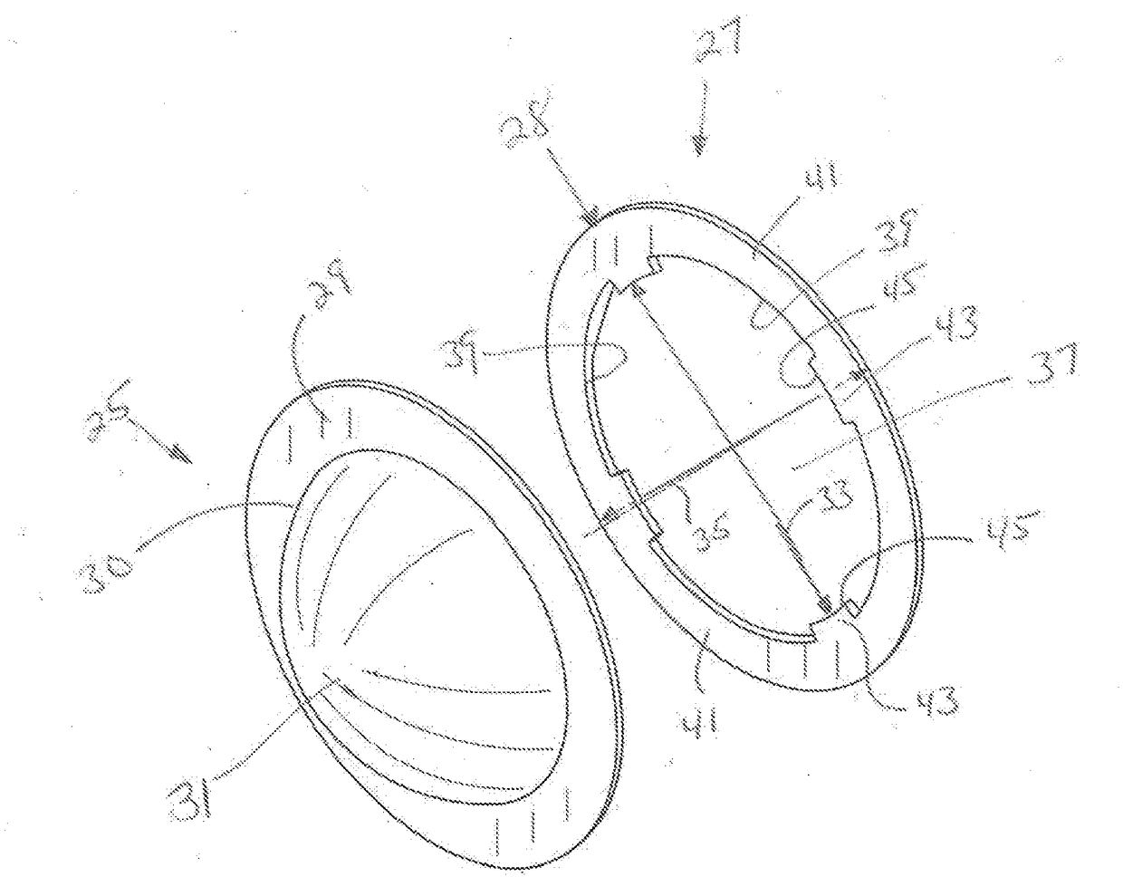
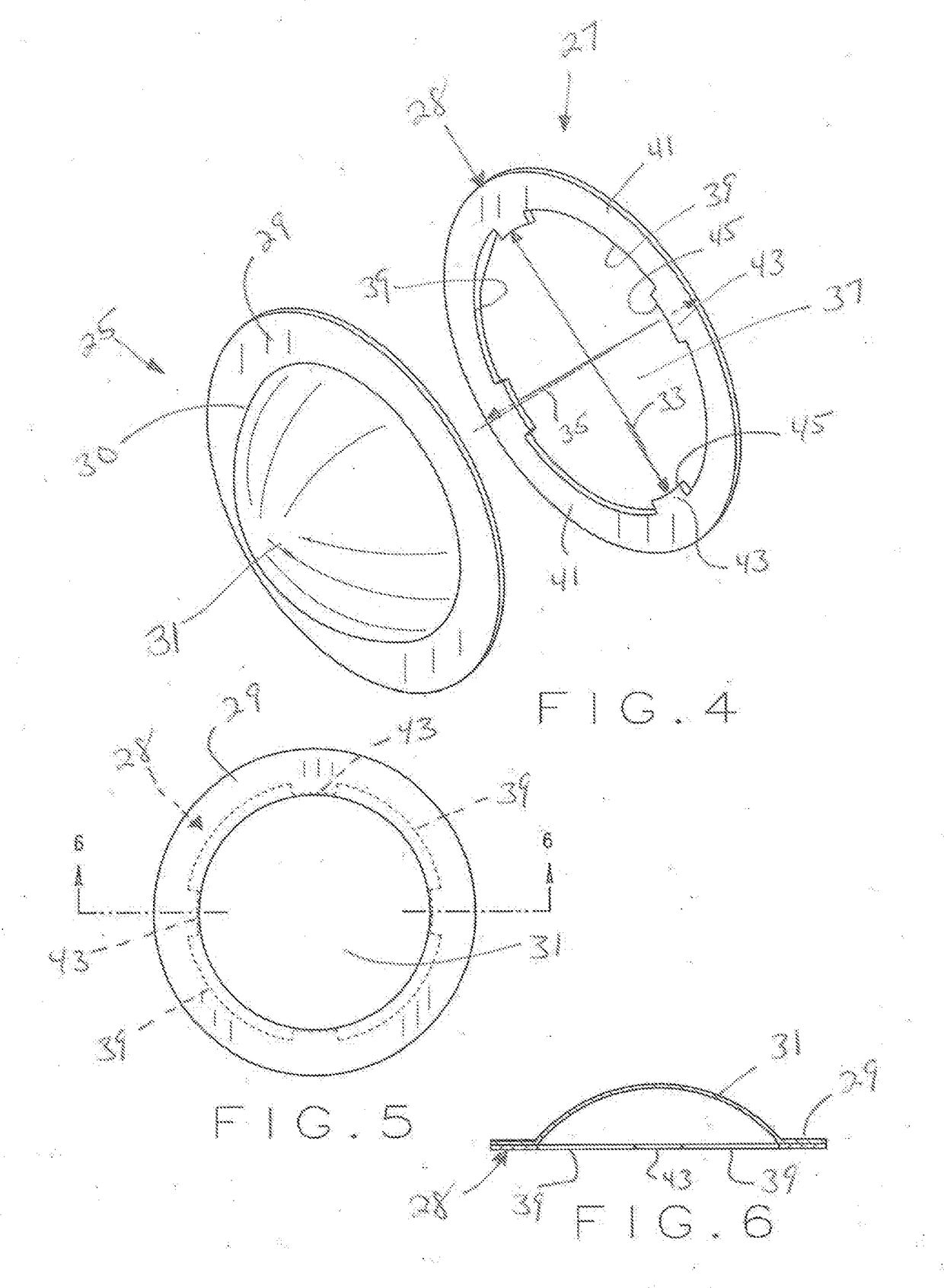
[0032]Referring to the drawings wherein like members refer to like parts, FIG. 4 illustrates one embodiment of the present inlet support structure 27 positioned for use with a prior art rupture disc 25. Rupture disc 25 is substantially similar to the prior art rupture disc 1 (FIGS. 1-3) and includes an annular flat flange region 29, a transition region 30 and a disc dome 31 that are each substantially similar to the prior art annular flat flange region 5, the transition region 6, and disc dome 7, respectively. The rupture disc 25 may likewise be provided with a deformation in the form of dimples, score lines, or other weakening elements to facilitate the rupture of the rupture disc 25. The present support member 27 is constructed according to the teachings of the present invention and again acts as a support member or holder for the rupture disc 25 in a manner substantially similar to the prior art support member 3. As will be hereinafter explained, the present support member 27 inc...


PUM


Abstract

An inlet support structure for use with a rupture disc, the inlet support structure including an annular member having an inner diameter, an outer diameter, a plurality of spaced apart cut-outs extending from the inner diameter towards the outer diameter, a central non-circular opening extending through the annular member and including the cut-outs, the cut-outs providing additional space for the petals of a rupture disc to be received therein when the rupture disc ruptures so as to provide a greater flow area through the rupture disc.

Description

BACKGROUND OF THE INVENTION[0001]Devices for relieving high pressures within an over-pressurized system or vessel have been used in industry for many years. These devices, which are commonly known as rupture discs, provide a safety mechanism to relieve excess pressure from an over-pressurized system or vessel when a potentially dangerous over-pressure exists within the system. The rupture discs are typically placed within a vent or a pressure vessel of the system so as to prevent flow of fluid through the vent until an overpressure condition actually occurs. Each rupture disc is specifically designed to rupture at a pre-determined pressure and temperature thus relieving the pressure within the particular system.[0002]Rupture discs typically include a disc dome and so called tension-type rupture discs (in contrast to so-called reverse bucking discs) are typically oriented in a particular system such that the disc dome points away from the pressure side of the vent such that pressure ...

Claims


Application Information

Patent Timeline
Patent Type & Authority Applications(United States)
IPC IPC(8): F16K17/40
CPCF16K17/40F16K17/16F16K17/162Y10T137/1692Y10T137/1729F16K17/1626
Inventor PITTEL, BRIAN FRANCISMCCAMIS, J. KYLE
Owner CONTINENTAL DISC CORP
Why Eureka
Try Eureka