Edge detection with shutter adaption

Active Publication Date: 2018-03-01
PIXART IMAGING PENANG
View PDF3 Cites 2 Cited by
  • Summary
  • Abstract
  • Description
  • Claims
  • Application Information

AI Technical Summary

Benefits of technology

The invention aims to improve the accuracy of calculating the location of the leading edge when using different auto shutter speeds.

Problems solved by technology

This inaccuracy leads to difficulties when an optical mouse uses a sensor with auto shutter adaptation.

Method used


Image

  • Edge detection with shutter adaption
  • Edge detection with shutter adaption
  • Edge detection with shutter adaption

Examples


Embodiment Construction

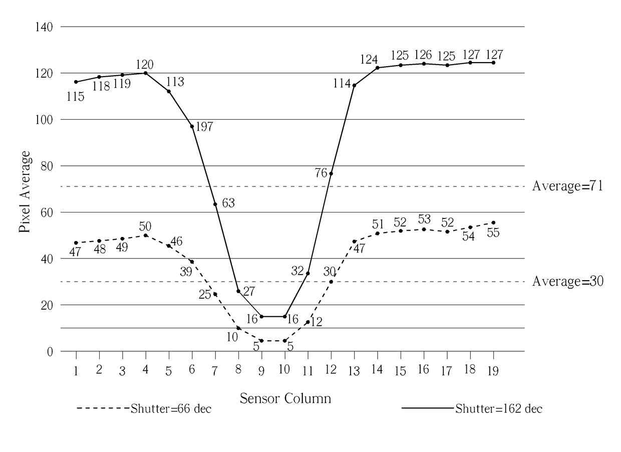
[0016]As detailed above, the present invention uses a sensor ADC distribution, rather than a sensor ADC range, as a means for determining edge location. This reduces inaccuracies between sensors of different shutter speeds, as the sensor distribution is not affected by shutter adaptation. Further, adaptive thresholds, corresponding to the particular shutter speed, will be applied.

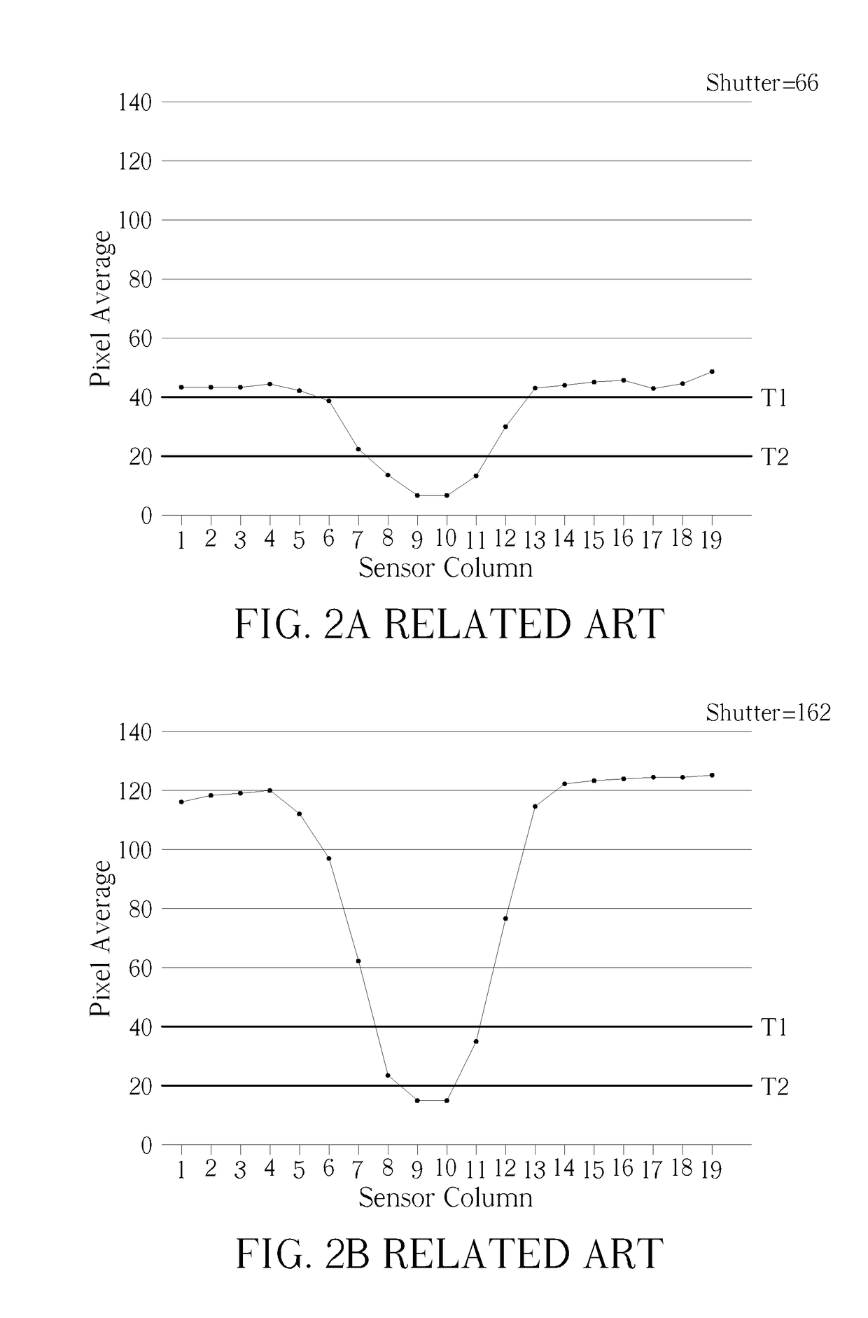
[0017]Please refer to FIG. 3, which illustrates pixel averages for sensor columns according to sensor shutter speeds 66 dec and 162 dec. The 66 dec shutter speed is illustrated by the dashed line, and the 162 dec shutter speed is illustrated by the solid line. Rather than defining two thresholds T1 and T2, wherein both shutter speeds use the same value T1 and T2 for determining an area defining a leading edge location, an average value between a maximum and minimum pixel value is defined for each shutter speed. The calculations for both shutter speeds are shown below.

For sensor shutter=66 dec

Maximum pixel v...


PUM


Abstract

A method for determining leading edge location in an image captured by an optical navigation sensor with auto shutter adaptation includes: plotting average pixel values per sensor column on a graph; determining an average value according to the average pixel values as a threshold value; defining a weighted location in the leading half of the captured image according to the threshold value; and determining the leading edge location according to the defined weighted location.

Description

BACKGROUND OF THE INVENTION1. Field of the Invention[0001]The invention relates to edge detection in an optical navigation sensor, and more particularly, to edge detection in an optical navigation sensor which can maintain accuracy when the shutter frequency changes.2. Description of the Prior Art[0002]Edge detection is a technique used in optical navigation sensors, such as those found in optical mice, which utilizes pixel imaging and discontinuities in pixel intensity to determine when an area has been crossed. Standard edge detection relies on two fixed thresholds, which define a grey region within an image. Please refer to FIG. 1, which is a diagram illustrating edge detection according to the prior art. As shown in FIG. 1, a captured image will have different pixel values when an edge is crossed. Two thresholds, T1 and T2, are defined which respectively illustrate the point at which a white region becomes a grey region, and the point at which the grey region becomes a dark regi...

Claims


Application Information

Patent Timeline
IPC IPC(8): G06T7/00G06T7/60
CPCG06T7/0085G06T2207/20112G06T7/60G06T7/004G06F3/0317G06T7/13G06T7/70
Inventor LEE, SIEW CHIN
Owner PIXART IMAGING PENANG
Why Eureka
Try Eureka