System and method for augmenting a primary powerplant

a technology of powerplants and power systems, applied in the direction of machines/engines, mechanical equipment, transportation and packaging, etc., can solve the problems of reducing engine efficiency, slowing down (or slowing down) rpms, and accelerating rpms

Inactive Publication Date: 2018-05-03
THE BOEING CO
View PDF11 Cites 23 Cited by
  • Summary
  • Abstract
  • Description
  • Claims
  • Application Information

AI Technical Summary

Problems solved by technology

Typically, the efficiency of the engine (e.g., compressors and turbines of the engine) is a first order function of the revolutions per minute (RPM), and running at slower (or faster) RPMs than their aerodynamic optima reduces engine efficiency.

Method used


Image

  • System and method for augmenting a primary powerplant
  • System and method for augmenting a primary powerplant
  • System and method for augmenting a primary powerplant

Examples


Embodiment Construction

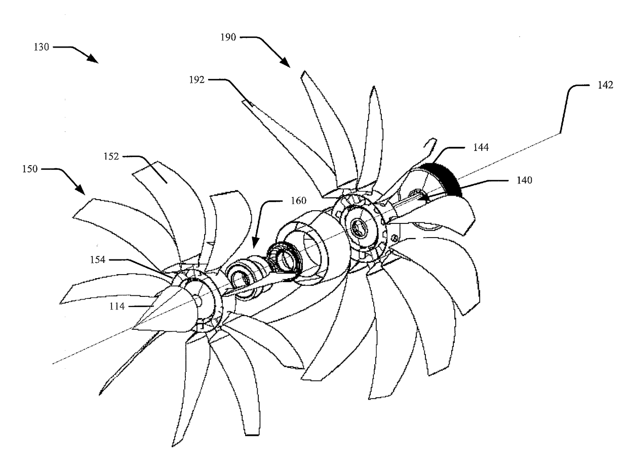
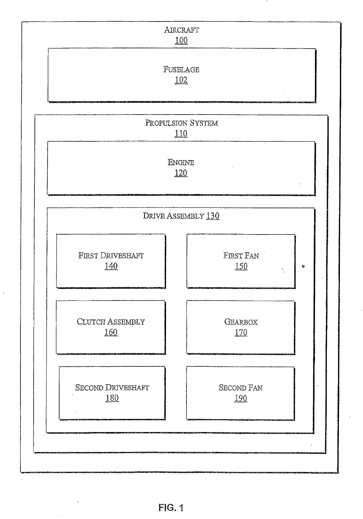
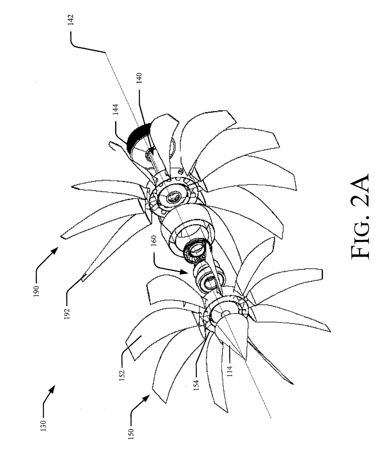
[0026]Implementations disclosed herein are directed to a propulsion system including two sources of power to operate an aircraft. A primary powerplant (e.g., a gas turbine engine) is the primary source of power and is operable during all phases of operation. An augmenting powerplant (e.g., a hydraulic motor, a pneumatic motor, or an electric motor) is a secondary source of power during certain phases of operation.

[0027]As an illustrative, non-limiting example, during a first flight stage (e.g., takeoff), energy stored within an accumulator is provided to a hydraulic motor and the combined power of the primary powerplant and the hydraulic motor provides sufficient thrust during takeoff to meet Federal Aviation Regulations (e.g., FAR 25.111 et al). During cruise conditions, the power from the hydraulic motor is not needed, and the primary powerplant provides power to generate thrust. The augmenting powerplant enables the primary powerplant to be designed and sized (e.g., optimized) fo...


PUM


Abstract

An aircraft propulsion system includes a fan, a primary powerplant, an augmenting powerplant and a controller. The primary powerplant is coupled to the fan and configured to rotate the fan during a first flight stage and during a second flight stage. The augmenting powerplant is coupleable with the fan. The controller is configured to cause the augmenting powerplant to drive the fan during the first flight stage, and to cause the augmenting powerplant to cease driving the fan based on an indication of a transition from the first flight stage to the second flight stage.

Description

FIELD OF THE DISCLOSURE[0001]The present disclosure is generally related to a propulsion system including an augmenting powerplant.BACKGROUND[0002]When designing an aircraft, engines are designed in accordance with Federal Aviation Regulations (FAR). Aircraft engines are typically sized by takeoff thrust requirements & one-engine inoperative climb thrust requirements of the FAR. These requirements result in an aircraft engine (e.g., an engine core) that is able to cycle larger quantities of air (i.e. have a higher air mass-flow rate) during takeoff operations and climb operations than is optimal for cruise operations. A diameter of rotating machinery within the engine core is based on a maximum mass-flow rate. Thus, an aircraft engine core satisfying the takeoff and climb thrust requirements may have a larger diameter than is optimal for cruise operations. During a cruise flight stage, a rotation rate of the turbo-mechanical components of the engine is lowered to achieve the mass-fl...

Claims


Application Information

Patent Timeline
Patent Type & Authority Applications(United States)
IPC IPC(8): B64D35/08B64D27/16B64D27/24B64D31/06F02C6/06
CPCB64D35/08B64D27/16B64D27/24B64D31/06F05D2260/4023B64D2027/026F05D2220/323F05D2220/70F02C6/06B64D27/02F02C7/36F02K5/00F02C7/32F02K3/04Y02T50/60
Inventor GOLSHANY, SINA S.ERICKSON, TODD W.ALDERKS, DEREK R.
Owner THE BOEING CO
Why Eureka
Try Eureka