
LED bulb lamp

a technology of led light bulbs and led bulbs, which is applied in the field of lighting, can solve the problems of unfavorable lighting effect, concentrated light effect, and difficult to create the effect of even illumination light, and achieve the effect of small size and long service li

Active Publication Date: 2018-05-03
ZHEJIANG SUPER LIGHTING ELECTRIC APPLIANCE
View PDF0 Cites 13 Cited by
  • Summary
  • Abstract
  • Description
  • Claims
  • Application Information

AI Technical Summary

Benefits of technology

The LED light bulb described in this patent has a unique design that allows for a symmetrical distribution of light rays, resulting in an even and wide illumination. This design feature creates an omnidirectional light effect, which is beneficial for various lighting applications.

Problems solved by technology

As previously discussed, commercially available LED light bulbs have some drawbacks.
Concentration of light rays result in uneven, concentrated light effect.
Under the circumstances that there is only one LED filament inside an LED light bulb, it is hard to create the effect of even illumination light.

Method used


Image

  • LED bulb lamp
  • LED bulb lamp
  • LED bulb lamp

Examples


Embodiment Construction

[0069]In order to make the objects, technical solutions and advantages of the invention more apparent, the invention will be further illustrated in details in connection with accompanying figures and embodiments hereinafter. It should be understood that the embodiments described herein are just for explanation, but not intended to limit the invention.

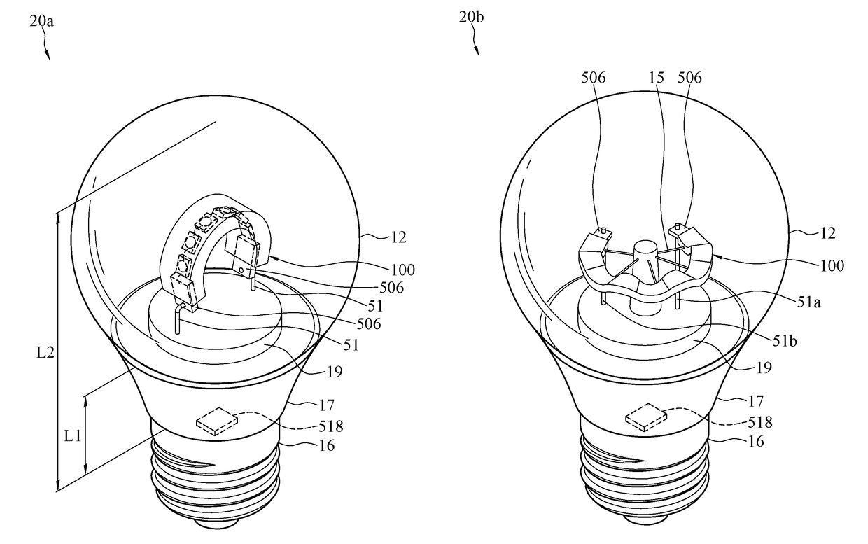
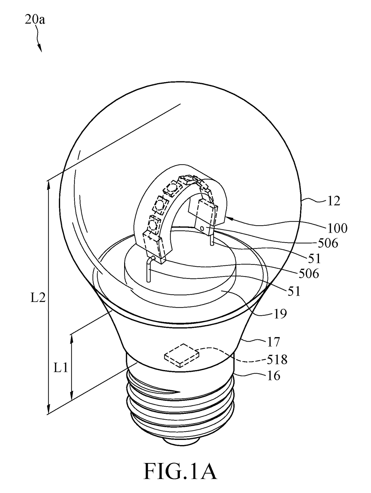
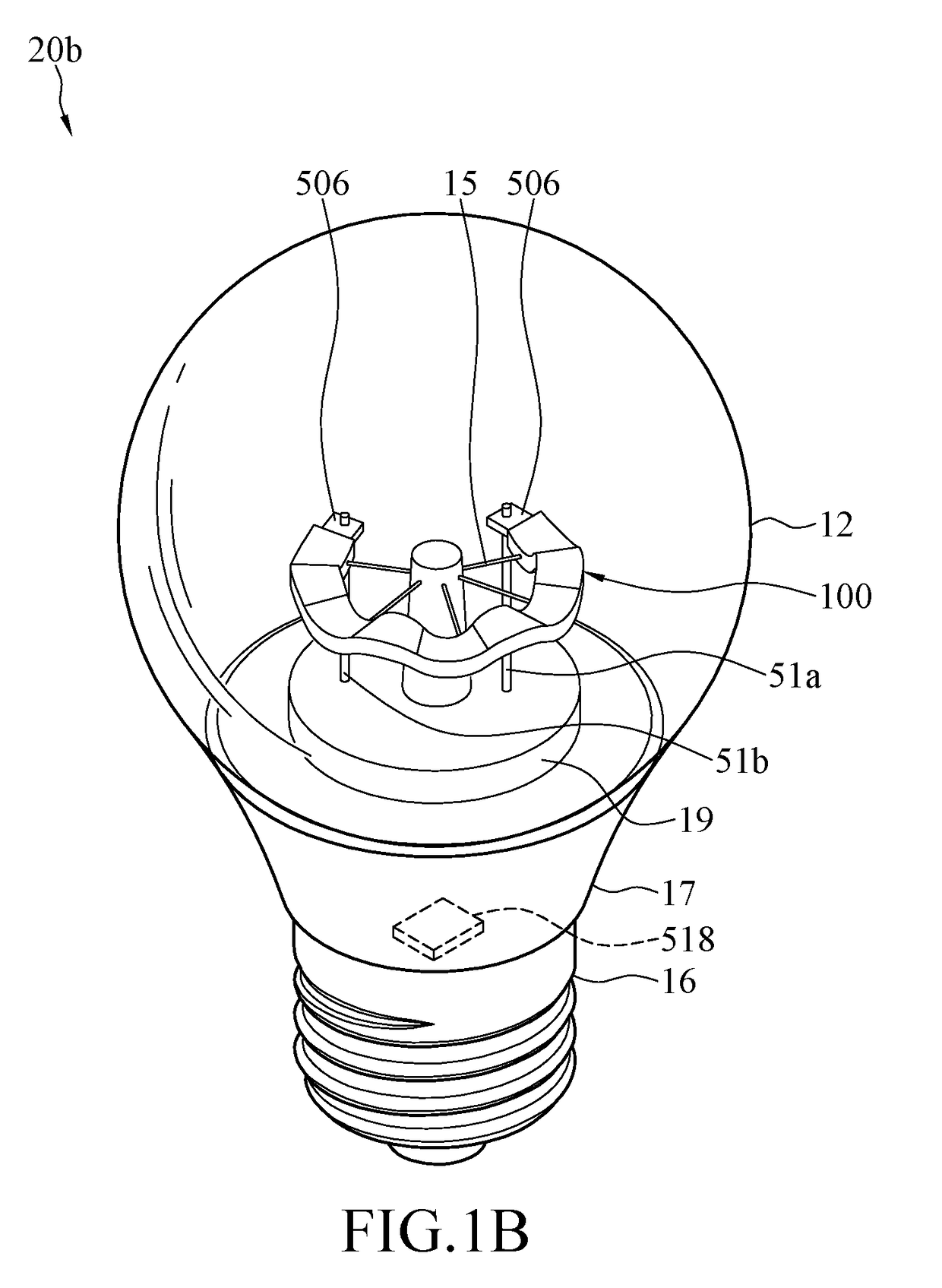
[0070]Please refer to FIGS. 1A and 1B which illustrate a perspective view of LED light bulb applying the LED filaments according to the first embodiment and the second embodiment. The LED light bulb 20a, 20b comprises a bulb shell 12, a bulb base 16 connected with the bulb shell 12, at least two conductive supports 51a, 51b disposed in the bulb shell 12, a driving circuit 518 electrically connected with both the conductive supports 51a, 51b and the bulb base 16, and a single LED filament 100 disposed in the bulb shell 12. The LED filament 100 comprises LED chips aligned along a line.

[0071]The conductive supports 51a, 51b are used for el...


PUM


Abstract

An LED light bulb includes a bulb shell, a bulb base, two conductive supports, a stem, and an LED filament. The bulb base is connected with the bulb shell. The two conductive supports are disposed in the bulb shell. The stem extends from the bulb base to inside of the bulb shell. The LED filament includes a plurality of LED chips and two conductive electrodes. The LED chips are arranged in an array along an elongated direction of the LED filament. The two conductive electrodes are respectively disposed at two ends of the LED filament and connected to the LED chips. The two conductive electrodes are respectively connected to the two conductive supports. The LED filament is curled to satisfy symmetry characteristics. Brightness presented by portions of the LED filament in different quadrants in a top view or in a side view is in line symmetry or in point symmetry.

Description

CROSS-REFERENCE TO RELATED APPLICATIONS[0001]This application is a continuation-in-part application of U.S. application Ser. No. 15 / 499,143 filed on 2017 Apr. 27, which claims priority to Chinese Patent Applications No. 201510502630.3 filed on 2015 Aug. 17; No. 201510966906.3 filed on 2015 Dec. 19; No. 201610041667.5 filed on 2016 Jan. 22; No. 201610272153.0 filed on 2016 Apr. 27; No. 201610394610.3 filed on 2016 Jun. 3; No. 201610586388.7 filed on 2016 Jul. 22; No. 201610544049.2 filed on 2016 Jul. 7; No. 201610936171.4 filed on 2016 Nov. 1; No. 201611108722.4 filed on 2016 Dec. 6; No. 201610281600.9 filed on 2016 Apr. 29; No. 201710024877.8 filed on 2017 Jan. 13; No. 201710079423.0 filed on 2017 Feb. 14; No. 201710138009.2 filed on 2017 Mar. 9; No. 201710180574.5 filed on 2017 Mar. 23; and No. 201710234618.8 filed on 2017 Apr. 11, each of which is incorporated herein by reference in its entirety.[0002]This application is a continuation-in-part application of U.S. application Ser. ...

Claims


Application Information

Patent Timeline
Patent Type & Authority Applications(United States)
IPC IPC(8): F21K9/232H05B33/08H05B44/00
CPCF21K9/232H05B33/0806F21V15/04H05B45/00H05B45/10F21Y2107/00
Inventor JIANG, TAOCHEN, YI-CHING
Owner ZHEJIANG SUPER LIGHTING ELECTRIC APPLIANCE
Learn More