LED device and LED lamp including the same

Active Publication Date: 2018-08-02
SAMSUNG ELECTRONICS CO LTD
View PDF5 Cites 12 Cited by
  • Summary
  • Abstract
  • Description
  • Claims
  • Application Information

AI Technical Summary

Benefits of technology

[0007]An aspect of the present disclosure may provide a light emitting diode (LE

Problems solved by technology

However, a problem in which incandescent lamps or fluorescent lamps may need to be frequently replaced due to a relatively short lifespan thereof is present.
In other words, since LEDs have relatively high photoelectric conve

Method used


Image

  • LED device and LED lamp including the same
  • LED device and LED lamp including the same
  • LED device and LED lamp including the same

Examples


Embodiment Construction

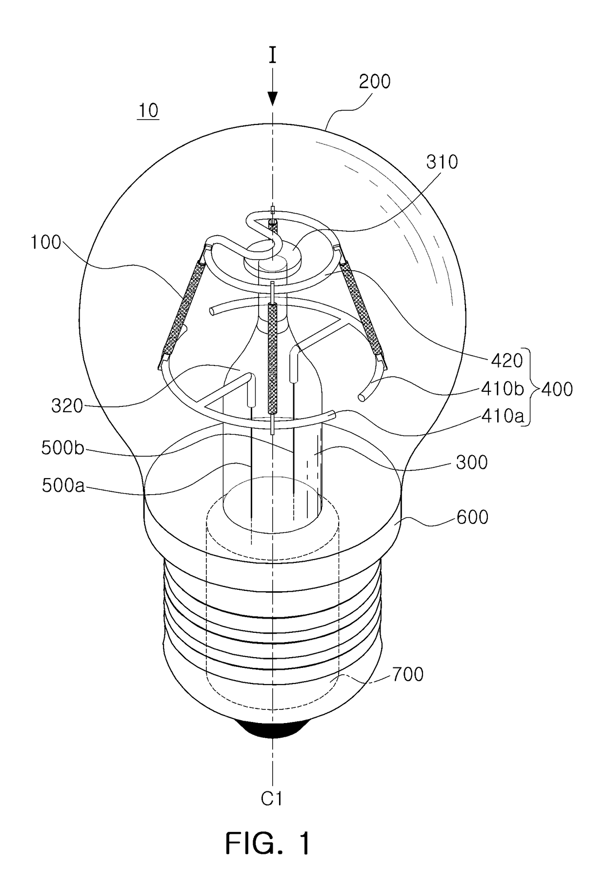
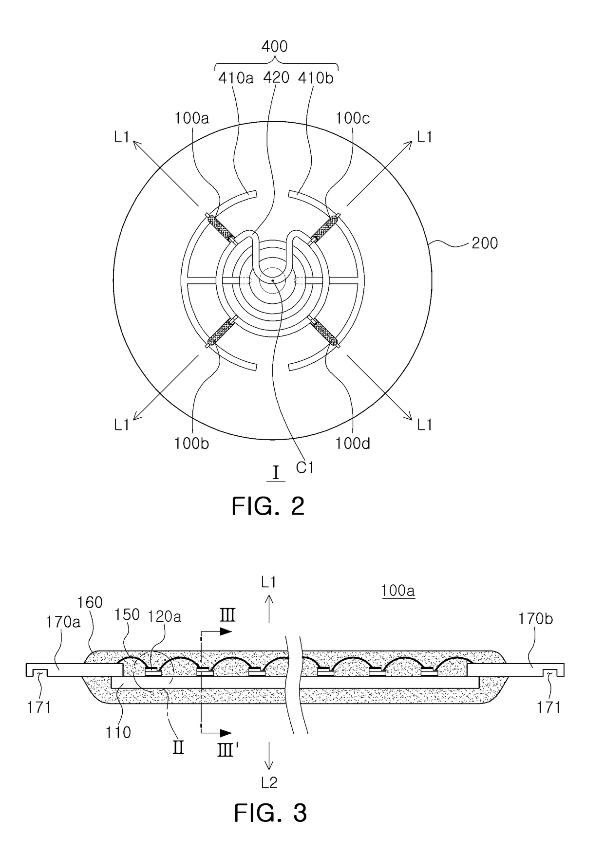
[0024]FIG. 1 is a perspective view of a light emitting diode (LED) lamp according to an example embodiment of the present disclosure, while FIG. 2 is a top view taken in direction I of FIG. 1. In an example embodiment, the direction I in FIG. 1 also indicates a central axis of the LED lamp.

[0025]With reference to FIGS. 1 and 2, an LED lamp 10 may include a bulb 200, a base portion 600, e.g., a base, coupled to an end of the bulb 200, e.g., the base is disposed below the bulb 200, and a plurality of LED devices 100 accommodated in an internal space of the bulb 200. In an example embodiment, a first center of the bulb 200 and a second center of the base are disposed along the central axis, and the plurality of LED devices 100 are disposed inside the bulb 200 and disposed about the central axis.

[0026]The bulb 200 may be provided as a transparent, milky, lusterless, colored bulb cover formed using glass, hard glass, quartz glass, or a light transmissive resin. The bulb 200 may be provid...


PUM


Abstract

An LED device includes a transparent substrate having a bar-like shape and having a first surface and a second surface opposed thereto, a plurality of LED chips mounted on the first surface of the transparent substrate and electrically connected to each other, each of the plurality of LED chips having a reflective layer disposed on a surface mounted in the transparent substrate, a first connection terminal and a second connection terminal disposed on opposing ends of the transparent substrate and electrically connected to the plurality of LED chips, a bonding layer interposed between the plurality of LED chips and the transparent substrate and including a metal filler, and a wavelength conversion portion covering the first surface and the second surface of the transparent substrate and the plurality of LED chips.

Description

CROSS-REFERENCE TO RELATED APPLICATION[0001]This application claims the benefit of Korean Patent Application No. 10-2017-0013794, filed on Jan. 31, 2017, with the Korean Intellectual Property Office, the disclosure of which is incorporated herein by reference in its entirety.BACKGROUND1. Field[0002]The present disclosure relates to a light emitting diode (LED) device and an LED lamp including the same.2. Description of Related Art[0003]In general, incandescent lamps or fluorescent lamps have been commonly used as indoor or outdoor lighting devices. However, a problem in which incandescent lamps or fluorescent lamps may need to be frequently replaced due to a relatively short lifespan thereof is present.[0004]In order to solve such a problem, lighting apparatuses, including LEDs, having characteristics such as excellent controllability, relatively high response speeds, relatively high photoelectric conversion efficiency, relatively long lifespans, a relatively low level of power cons...

Claims


Application Information

Patent Timeline
IPC IPC(8): F21K9/232H01L25/075H01L33/06H01L33/32H01L33/60H01L33/50H01L33/56H01L33/62H01L33/64F21K9/27
CPCF21K9/232H01L25/0753H01L33/06H01L33/32H01L33/60F21Y2115/10H01L33/56H01L33/62H01L33/641F21K9/27H01L33/502F21K9/238F21K9/68F21V19/0025F21V23/06H01L33/505H01L2224/49107H01L2224/73265F21V3/02F21K9/23F21Y2107/00F21K9/64F21V7/22H01L33/10H01L2924/12041
Inventor CHUNG, JIN WOOKHWANG, KYUNG WOOK
Owner SAMSUNG ELECTRONICS CO LTD
Why Eureka
Try Eureka