Interferometric radar with rotating antenna

an interferometer and antenna technology, applied in the direction of instruments, measurement devices, and using reradiation, can solve the problems of not being able to provide sars with the ability to measure small displacements for monitoring hillsides or buildings

Active Publication Date: 2018-08-02
UNIVERSITY OF FLORENCE
View PDF0 Cites 6 Cited by
  • Summary
  • Abstract
  • Description
  • Claims
  • Application Information

AI Technical Summary

Benefits of technology

[0010]A first advantage of the invention lies in the fact that the interferometric radar proposed

Problems solved by technology

In this system, SAR synthesis occurs using the entire circumference, providing azimuth and elevation information, but with marked secondary lobes due to sampling on a closed line, and can hence be used for surveillance purposes, i.e., for detection of pointlike objects (aeroplanes or ships), but is not suitable for measuring small displacements for monitoring hillsides or buildings.
The known solutions present some significant drawbacks in the context of th

Method used


Image

  • Interferometric radar with rotating antenna
  • Interferometric radar with rotating antenna
  • Interferometric radar with rotating antenna

Examples


Embodiment Construction

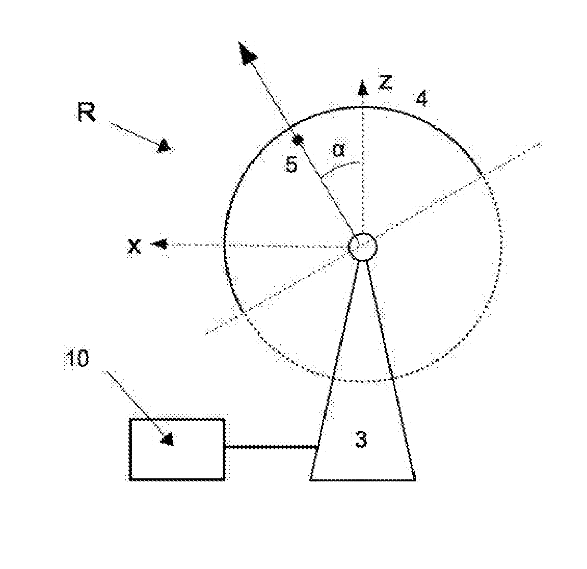
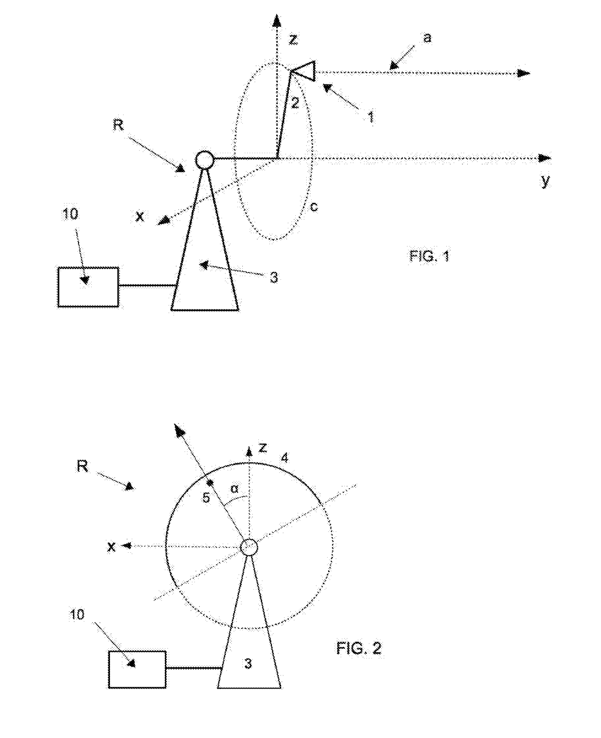
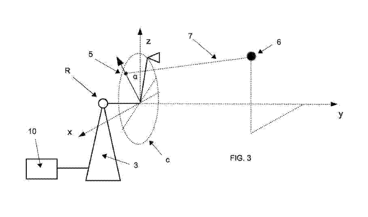
[0017]With reference to the attached drawings, a radar R according to the invention is described, which comprises a data-acquisition and processing unit 10, which receives the data detected by at least one antenna 1, which rotates in the plane zx orthogonal to the direction of sight y of the antenna and is fixed to an arm 2 that can be set in rotation by a motor-drive support 3.

[0018]In a first embodiment, the antenna 1 comprises a single linear-polarization antenna 1, but the antenna 1 may be equivalently constituted by two linear-polarization antennas (one for transmitting and one for receiving).

[0019]In a further embodiment, the antenna may comprise a single circular-polarization antenna or two circular-polarization antennas (one for transmitting and one for receiving). In addition, in an equivalent way, the circular-polarization antenna may be constituted by a system of polarimetric antennas.

[0020]In operation, the rotating element 2 is set in rotation, and a single image is obt...


PUM


Abstract

An interferometric radar comprising an arm (2), which rotates with respect to an axis (z) of a plane (zx) orthogonal to an axis of rotation (y), a system of linear-polarization antennas (1), which is fixed to said arm (2) for describing complete revolutions along a circular path (c) about said axis (y) and is oriented in a direction of sight (a) parallel to the axis (y), motor-drive means (3) for driving the arm (2), a data-acquisition and processing unit (10) operatively connected to said antenna (1) for acquiring a succession of images detected by the antenna during its revolution about the axis (y) and making differential interferometric calculations for measuring at least one component of the displacement of one or more targets in the field of view, or else for measuring the digital elevation map (DEM) of the scenario in the field of view.

Description

[0001]The invention relates to an interferometric radar and in particular an interferometric radar with rotating antenna with a direction of sight orthogonal to the plane of rotation.PRIOR ART[0002]Interferometric radars referred to as GB-SARs (Ground-Based Synthetic-Aperture Radars) devised in particular for monitoring structures of large dimensions such as hillsides, open-cast mines, large architectural structures, such as towers and bridges have been known for some time. GB-SAR technology is of particular interest because it constitutes a radar technique capable of providing high-precision displacement maps over an entire range of observation. In their basic conformation, conventional GB-SARs are obtained by moving an antenna along an axis, as described in the paper by M. Pieraccini, D. Tarchi, H. Rudolf, D. Leva, G. Luzi, C. Atzeni, Interferometric radar for remote monitoring of building deformations, Electronics Letters, Vol. 36, No. 6, pp. 569-570 (2000).[0003]The U.S. Pat. No...

Claims


Application Information

Patent Timeline
IPC IPC(8): G01S13/90G01S7/02
CPCG01S13/9023G01S7/025G01S2013/9088G01S13/9088
Inventor PIERACCINI, MASSIMILIANO
Owner UNIVERSITY OF FLORENCE
Why Eureka
Try Eureka