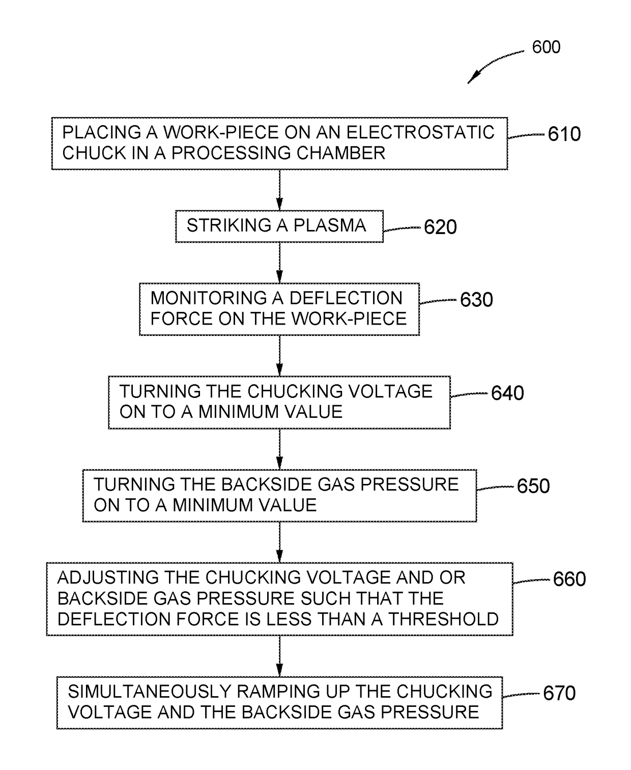
Real time monitoring with closed loop chucking force control
a technology of chucking force control and real-time monitoring, which is applied in the direction of semiconductor/solid-state device testing/measurement, plasma technique, electric discharge tubes, etc., can solve the problems of loose defects landed on the surface of the workpiece, the workpiece processing side can have quality problems, and the film stress in the workpiece increases, so as to minimize the chucking force
- Summary
- Abstract
- Description
- Claims
- Application Information
AI Technical Summary
Benefits of technology
Problems solved by technology
Method used
Image

Examples
Embodiment Construction
[0019]Reference will now be made in detail to the embodiments, examples of which are illustrated in the accompanying drawings, in which some, but not all embodiments are shown. Indeed, the concepts may be embodied in many different forms and should not be construed as limiting herein; rather, these embodiments are provided so that this disclosure will satisfy applicable legal requirements. Whenever possible, like reference numbers will be used to refer to like components or parts.
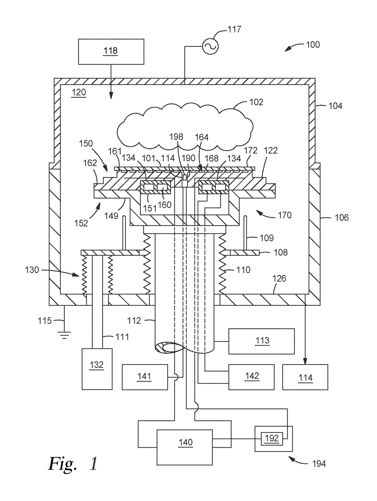
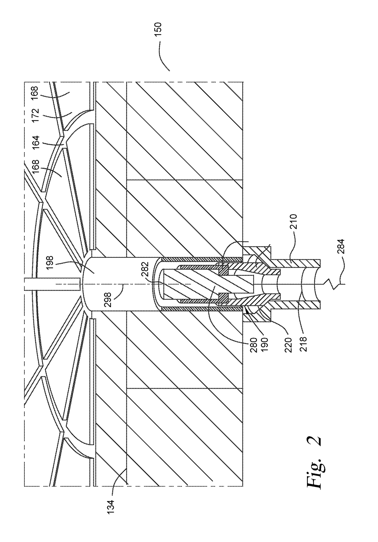
[0020]Embodiments disclosed herein include a sensor assembly that includes one or more of a sensor housing and a deflection sensor. The sensor assembly is configured to be disposed within a substrate support assembly, such as an electrostatic chuck configured with backside gas, or other suitable assembly for holding a workpiece while processing in a processing chamber. For example, the sensor assembly may be disposed in an existing backside gas delivery hole or other hole in the electrostatic chuck. The def...
PUM
 Abstract
Description
Claims
Application Information
 - R&D Engineer
- R&D Manager
- IP Professional
- Industry Leading Data Capabilities
- Powerful AI technology
- Patent DNA Extraction
Browse by: Latest US Patents, China's latest patents, Technical Efficacy Thesaurus, Application Domain, Technology Topic.
© 2024 PatSnap. All rights reserved.Legal|Privacy policy|Modern Slavery Act Transparency Statement|Sitemap