Mounting processing method, mounting system, exchange control device, and component mounter

a processing method and mounting system technology, applied in the direction of coupling device engagement/disengagement, electrical equipment, coupling device connection, etc., can solve the problem of delay in the production of the next type of board, and achieve the effect of curtailing any loss, efficient transferring component supply units, and improving productivity

Active Publication Date: 2018-12-27
FUJI CORP
View PDF15 Cites 8 Cited by
  • Summary
  • Abstract
  • Description
  • Claims
  • Application Information

AI Technical Summary

Benefits of technology

[0003]To solve such a problem of exchange time, performing exchange of component supply units automatically has been proposed (for example, PCT / JP2014 / 73093). In a component mounting system disclosed therein an exchange robot capable of automatically exchanging component supply units is provided. And, the exchange robot enables changeover of board type to be performed quickly by exchanging a component supply unit for which supplying of components has been completed with a component supply unit required for the next mounting processing during production of the pre-changeover board type. As such, in order to improve mounting processing productivity, it is demanded to perform exchange of component supply units efficiently.
[0004]Here, exchange of component supply units is not limited to when the board type is changed. In particular, with an item used as a unit exchanging device such as an exchange robot, compared to an operator exchanging component supply units, it is possible to exchange component supply units in various situations, further increasing the above demand for efficient exchange.
[0005]An object of the present disclosure is to improve productivity by efficiently exchanging component supply units during mounting processing using a unit exchanging device.Solution to Problem

Problems solved by technology

In this case, the time required for exchange work depends on the quantity of component supply units to be exchanged, and there are cases in which the start of production of the next type of board is delayed.

Method used


Image

  • Mounting processing method, mounting system, exchange control device, and component mounter
  • Mounting processing method, mounting system, exchange control device, and component mounter
  • Mounting processing method, mounting system, exchange control device, and component mounter

Examples


first embodiment

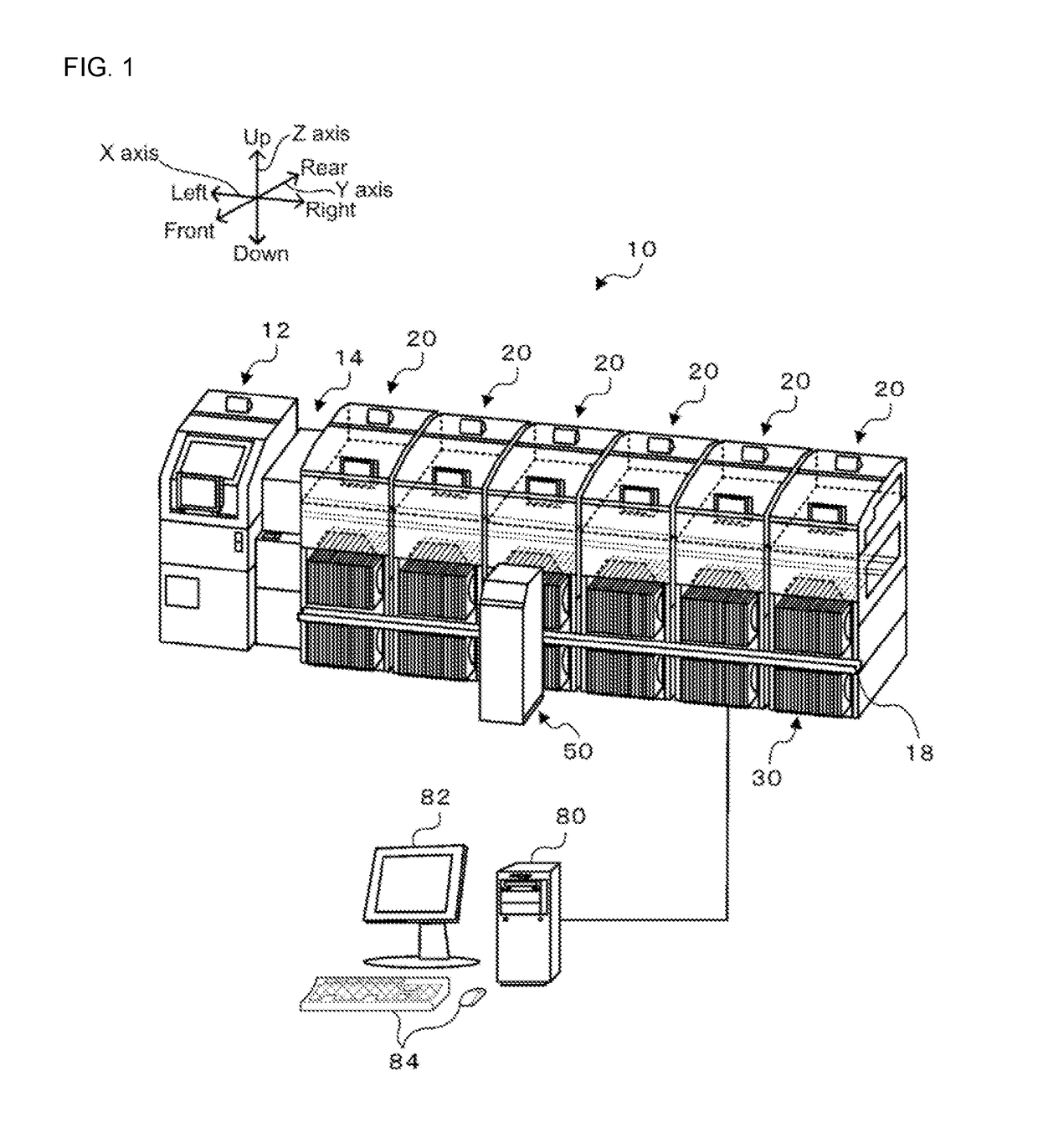
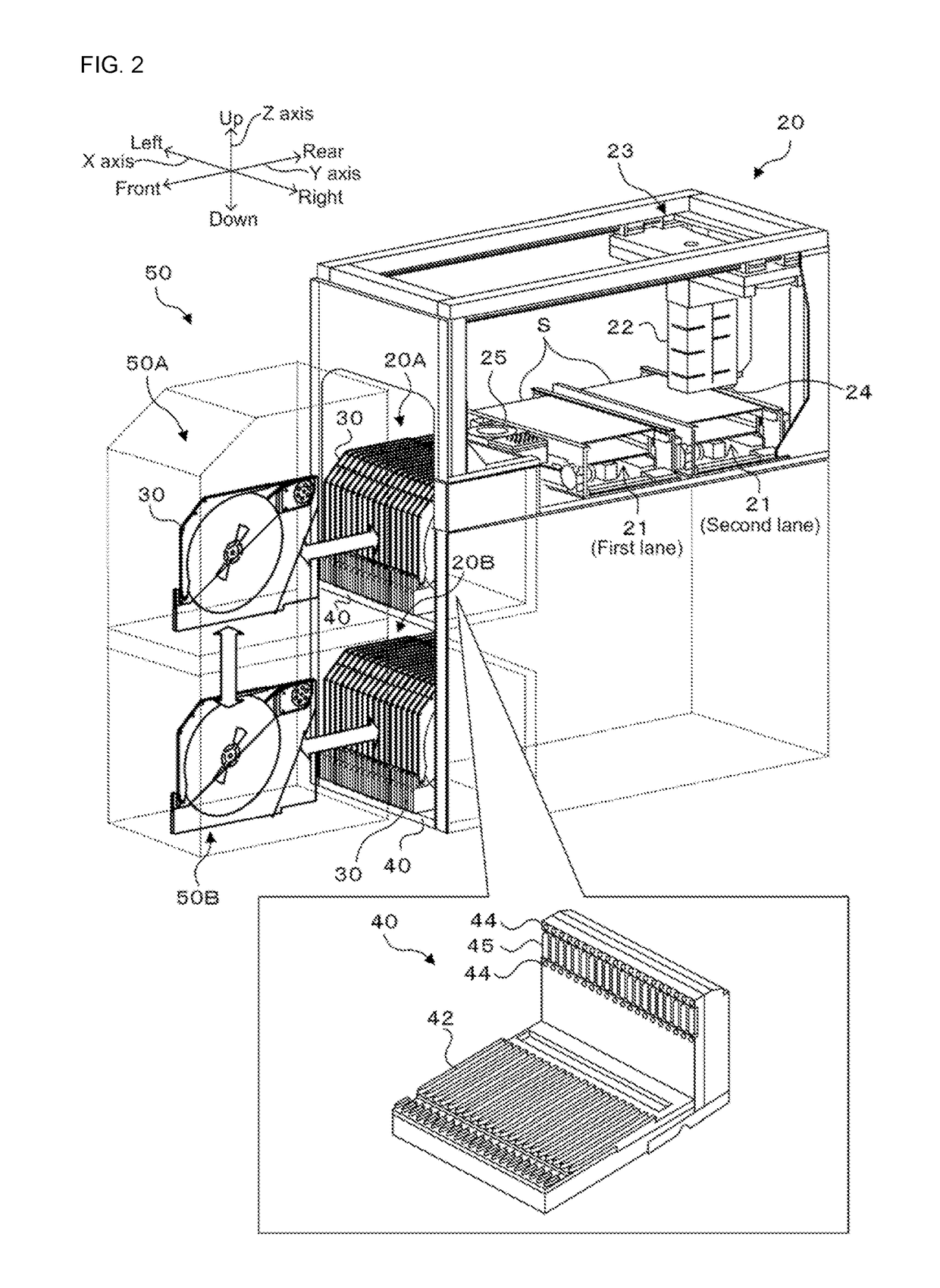
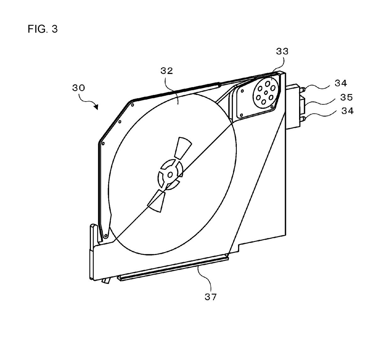
[0053]A first embodiment of the present disclosure is described below using the figures. FIG. 1 shows the overall configuration of component mounting system 10; FIG. 2 shows the overall configuration of component mounter 20; FIG. 3 shows the overall configuration of feeder 30. FIG. 4 shows the overall configuration of exchange robot 50; FIG. 5 shows the configuration of control related items of component mounting system 10. Note that, the left-right direction in FIG. 1 is the X direction, the front-rear direction is the Y direction, and the up-down direction is the Z direction.

[0054]As shown in FIG. 1, component mounting system 10 is provided with items such as printer 12 that prints solder on a board, print inspection machine 14 that inspects the state of printed solder, multiple component mounters 20 that mount components supplied from feeders 30 on a board, a mounting inspection machine (not shown) that inspects the mounting state of the components, and management device 80 that ...

second embodiment

[0084]A second embodiment of the present disclosure is described below. The configuration of component mounting system 10 (component mounter 20, exchange robot 50) of the second, third, and fourth embodiments is the same as that of the first embodiment, so descriptions are omitted. With the second embodiment, the initial setting related processing of FIG. 14 is performed instead of that of FIG. 8. With the processing of FIG. 14, CPU 80a of management device 80, first, acquires information of the board type for which mounting processing is to be performed, and the board type for which mounting processing is to be performed next (S200a). Note that, as described above, the information is information such as mounting target component types, mounting order of each component type, and quantity of feeders 30 required for mounting processing (component type quantity, required feeder quantity). Next, CPU 80a sets feeders 30 for all component types as initial set targets (S210). Note that, in...

third embodiment

[0093]A third embodiment of the present disclosure is described below. With the third embodiment, the initial setting related processing of FIG. 18 is performed instead of that of FIG. 8. With the processing of FIG. 18, CPU 80a of management device 80, first, acquires information related to the mounting target component types, the mounting order of the component types, and whether mixed loading of each component type is allowed (S200b), checks whether mixed loading of each component type is allowed (S260), and determines whether there is a component type for which mixed loading is not allowed (S262). Here, CPU 80a determines that mixed loading is not allowed for component types defined as not being allowed to be mixed based on component characteristics or components of a different production lot not being mounted within the same board (or components supplied from different feeders 30). For particular component types for which it is determined that mixed loading is not allowed, each ...


PUM


Abstract

A component mounting system starts mounting processing in a state in which a portion of the initial set target feeders of the multiple feeders required for mounting processing are set in supply area of component mounter, and in which remaining feeders are not set in supply area of component mounter. Mounting processing is performed while switching feeders that have finished supplying components with remaining feeders using exchange robot during mounting processing of a single board. By this, because it is possible to perform mounting processing while exchanging required feeders within the range of the upper limit loading quantity of component mounter, it is possible to improve the efficiency of mounting processing.

Description

TECHNICAL FIELD[0001]The present application relates to a mounting processing method, a mounting system, an exchange control device, and a component mounter.BACKGROUND ART[0002]Conventionally, component mounters that mount components, which are supplied by a component supply unit that houses multiple components, on a board are known. For example, with a component mounter of patent literature 1, multiple component supply units are arranged lined up along the conveyance direction of the board. With such a component mounter, when changing the type of board being produced, there are cases in which exchange work of component supply units is performed by an operator in accordance with the types of components required for mounting. In this case, the time required for exchange work depends on the quantity of component supply units to be exchanged, and there are cases in which the start of production of the next type of board is delayed.CITATION LISTPatent LiteratureBRIEF SUMMARYTechnical Pr...

Claims


Application Information

Patent Timeline
Patent Type & Authority Applications(United States)
IPC IPC(8): H05K13/08H05K13/04
CPCH05K13/086H05K13/0452H05K13/0419H05K13/0495H05K13/087H05K13/0882H05K13/0409H01R33/88H01R43/26H05K13/0417H05K13/085H05K13/0853
Inventor IISAKA, JUNOYAMA, SHIGETO
Owner FUJI CORP
Why Eureka
Try Eureka