Passive Electrostatic CO2 Composite Spray Applicator

a composite spray and electrostatic technology, applied in the direction of spray discharge apparatus, liquid supply arrangement, manufacturing tools, etc., can solve the problems of large portion of atomized spray missing the substrate, and wasting a portion of applied spray, etc., to achieve high melt point additive chemistries, improve spray process productivity, and reduce the effect of atomization

Active Publication Date: 2018-10-04
HITACHI HIGH-TECH CORP
View PDF4 Cites 7 Cited by
  • Summary
  • Abstract
  • Description
  • Claims
  • Application Information

AI Technical Summary

Benefits of technology

[0011]The present aspect provides an apparatus for producing an electrostatically charged and homogeneous CO2 composite spray containing an additive. The present invention overcomes the additive mixing and spray projection constraints of the prior art by positioning an additive injection and atomization nozzle into the center of and coaxial with two or more axis-symmetrically positioned and passively charged CO2 composite spray nozzles. The novel cluster spray arrangement with electrostatic field and velocity driven gradients for mixing additive and CO2 particles, and induced airflow to assist composite spray propulsion and delivery enables the formation of virtually any variety of CO2 composite fluid spray compositions. Uniquely, a multi-component CO2 composite fluid spray of the present invention is formed in space during transit to a target substrate, separated from the CO2 and additive particle injection means, to eliminate interferences introduced by phase change and direct contact charging phenomenon. Axis-symmetrically clustered CO2 sprays surrounding a centrally positioned additive spray flow creates adjustable and uniform electrostatic field and velocity gradients.
[0013]Another aspect of the present invention is to provide an apparatus and method for providing higher aerial and radial spray densities for a CO2 composite spray to improve spray process productivity. Advantages of CO2 composite sprays as compared to conventional CO2 snow sprays is the ability to adjust CO2 particle-in-propellant gas concentration, spray pressure, and spray mixture temperature. However, a limitation is low aerial and radial spray densities—spray area—for a CO2 spray applicator. This limits productivity in many industrial applications and the current technique used to overcome this limitation is to employ multi-ported wide-spray nozzle arrays. However as already discussed, conventional means for adding beneficial additives makes this type of arrangement very complicated and incompatible with high melt point additive chemistries.

Problems solved by technology

When low velocity sprays are employed, critical surfaces with recesses or complex surfaces cannot be penetrated effectively.
This phenomenon interferes with the even distribution of both CO2 coolant particles and oil-based lubricant on machined surfaces and causes a large portion of the atomized spray to miss the substrate entirely if positioned at a location too far away from the substrate being machined, wasting a portion of the applied spray.
The temperature of the CO2 particles (i.e., coolant) cause a flowing lubricant additive to solidify or gel prematurely before a uniform particle size and spray distribution can be established within the spray.
This is particularly the case when the mixing between the CO2 solid particles and additive particles occurs within the nozzle or near the nozzle tip, resulting in inconsistent spray patterns and chemistry, and the nozzle becoming clogged with frozen and agglomerated oil and additives.
However, as already noted this type of injection scheme introduces constraints for spray additives which are inherently incompatible with the physicochemistry of the CO2 spray at or near the spray forming nozzle.
For example, high spray pressure and velocity, very low temperature, and passive electrostatic charging within the CO2 particle nozzle body and exit introduce flow and mixing constraints for high melt point oils.
Exacerbating this problem is electrostatic fields and charges present during the formation and ejection of CO2 particles within and from the nozzle.
The result is a spray with compositional variance over time—large particle masses with low surface area or a complete lack of lubricating particles.

Method used


Image

  • Passive Electrostatic CO2 Composite Spray Applicator
  • Passive Electrostatic CO2 Composite Spray Applicator
  • Passive Electrostatic CO2 Composite Spray Applicator

Examples


Embodiment Construction

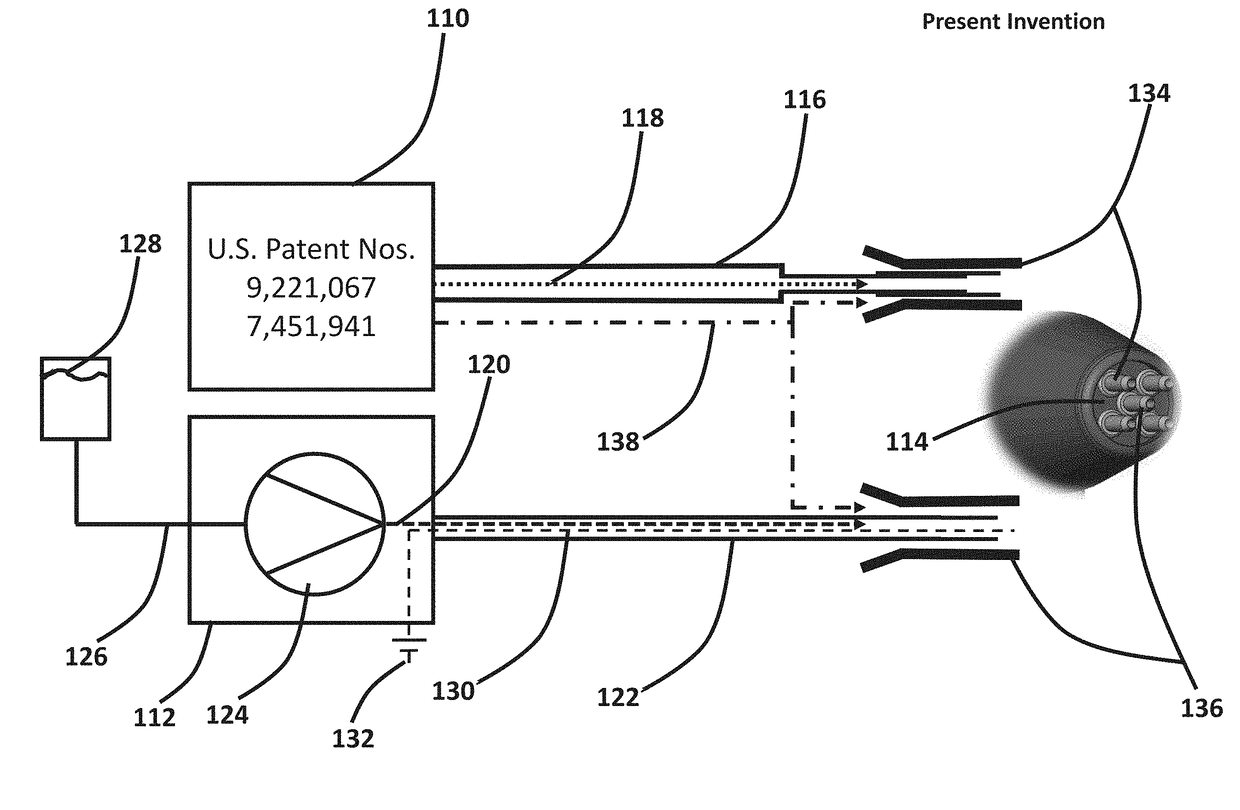
[0032]The present invention is an electrostatic spray application apparatus and method for producing an electrostatically charged and homogeneous CO2 composite spray mixture containing an additive and simultaneously projecting at a substrate surface. The CO2 composite spray mixture is formed in the space between CO2 and additive mixing nozzles and a substrate surface. The CO2 composite spray mixture is a composite fluid having a variably-controlled aerial and radial spray density comprising pressure- and temperature-regulated propellant gas (i.e., compressed air), CO2 particles, and additive particles. The invention comprises two or more circumferential and high velocity air streams containing passively charged CO2 particles which are positioned axis-symmetrically and coaxially about an inner and lower velocity injection air stream containing one or more additives to form a spray cluster. One or more spray clusters may be used to form a larger spray cluster configuration. The axis-s...


PUM

PropertyMeasurementUnit
lengthaaaaaaaaaa
lengthaaaaaaaaaa
pressureaaaaaaaaaa

Abstract

An electrostatic spray application apparatus and method for producing an electrostatically charged and homogeneous CO2 composite spray mixture containing an additive and simultaneously projecting at a substrate surface. The spray mixture is formed in the space between CO2 and additive mixing nozzles and a substrate surface. The spray mixture is a composite fluid having a variably-controlled aerial and radial spray density comprising pressure- and temperature-regulated propellant gas (compressed air), CO2 particles, and additive particles. There are two or more circumferential and high velocity air streams containing passively charged CO2 particles which are positioned axis-symmetrically and coaxially about an inner and lower velocity injection air stream containing one or more additives to form a spray cluster. The axis-symmetrical CO2 particle-air streams are passively tribocharged during formation, and the spray clustering arrangement creates a significant electrostatic field and Coanda air mass flow between and surrounding the coaxial flow streams.

Description

PRIORITY CLAIM[0001]This application claims the benefit of U.S. Provisional Patent Application No. 62 / 481,575, filed on Apr. 4, 2017, which is incorporated by reference in entirety.BACKGROUND OF INVENTION[0002]The present invention generally relates to spray applicators for forming and projecting a CO2 Composite Spray (a trademark of CleanLogix LLC). More specifically, the present invention relates to a passive electrostatic spray nozzle and spray applicator assembly employing air, solid carbon dioxide, and additive particles such as organic solvents, coatings, paints, nanoparticles, microabrasives, and lubricants.[0003]Use of CO2 composite sprays for cleaning, cooling and / or lubrication is widely known in the art. For example, CO2 composite sprays are typically employed during hard machining processes requiring cleaning, selective thermal control, and / or lubrication during turning, precision abrasive grinding, or dicing operations. In these applications, CO2 composite sprays are em...

Claims


Application Information

Patent Timeline
Patent Type & Authority Applications(United States)
IPC IPC(8): B05B5/03B05B5/025B05B5/16
CPCB05B5/032B05B5/0255B05B5/1683B24C1/003B24C11/005B05B7/0876B05B5/03B05B12/18
Inventor JACKSON, DAVID P.
Owner HITACHI HIGH-TECH CORP
Why Eureka
Try Eureka