
Method for manufacturing a hybrid component

a manufacturing method and technology of hybrid components, applied in the direction of manufacturing tools, turbines, transportation and packaging, etc., can solve the problems of increasing the cost of components, increasing the difficulty of manufacturing sx or ds parts/components by casting, and the anisotropy of material properties, etc., to achieve the effect of reducing the cost of components and increasing the process productivity

Inactive Publication Date: 2017-09-19
ANSALDO ENERGIA IP UK LTD
View PDF45 Cites 8 Cited by
  • Summary
  • Abstract
  • Description
  • Claims
  • Application Information

AI Technical Summary

Benefits of technology

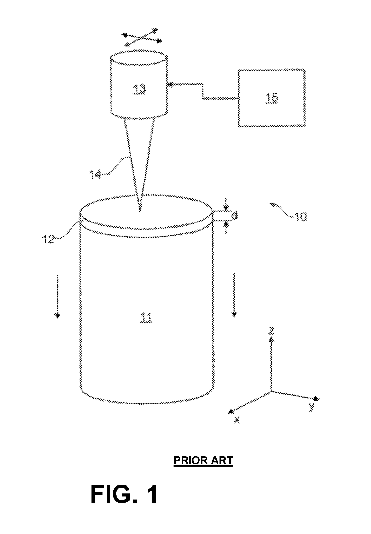
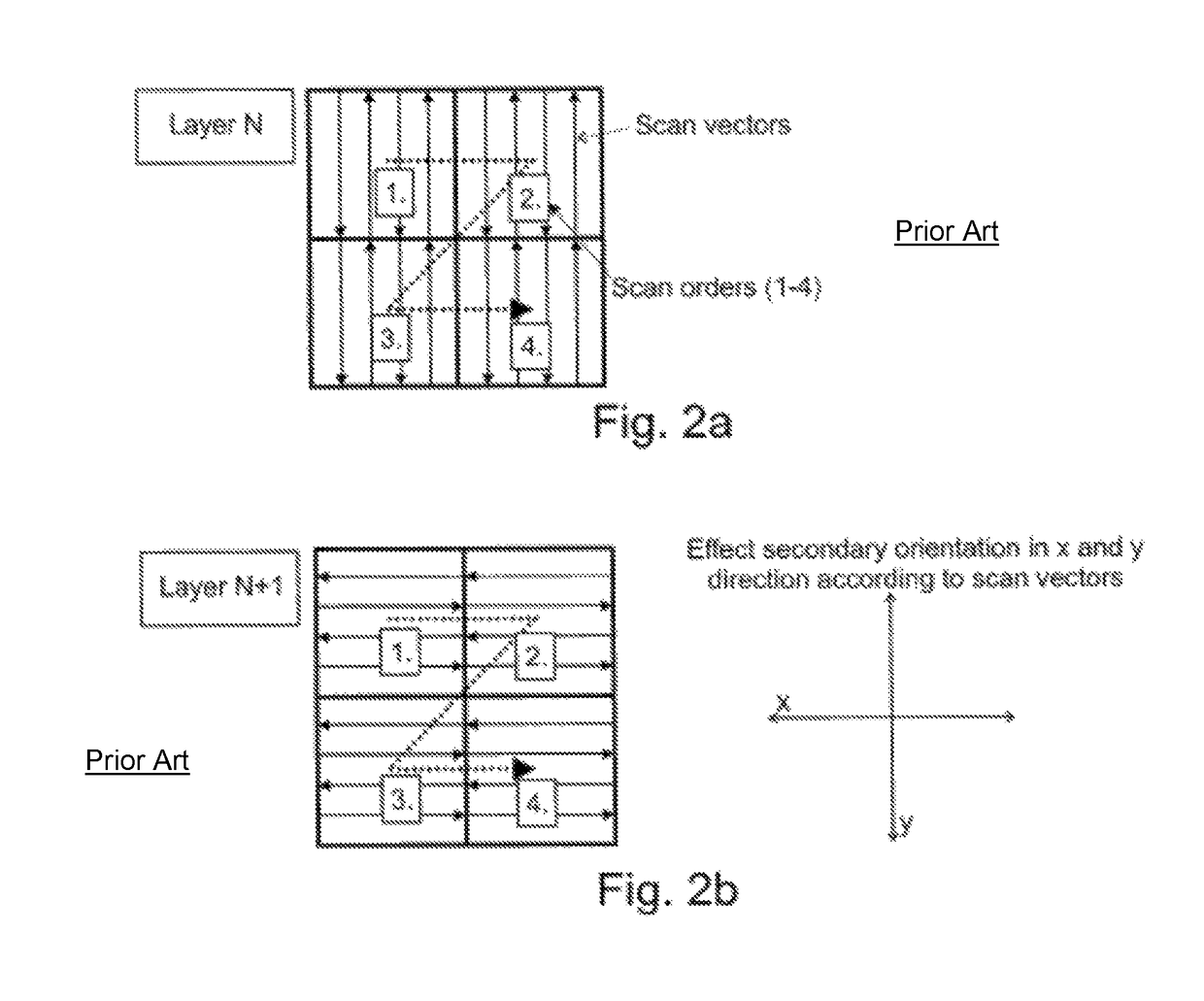
The present invention is aimed at developing a method for manufacturing a hybrid component with optimized properties that have an extended service lifetime compared to previous components. The method involves manufacturing preforms by traditional methods, such as casting, forging, or milling, or through additive manufacturing, and then controlling the secondary crystallographic grain orientation in the component to achieve improved properties. This method can be used for manufacturing hot gas parts, prototypes, and even for reconditioning or repair processes. The control of the microstructure is retained, allowing for different zones to have different mechanical requirements.

Problems solved by technology

Such anisotropy of material properties could be a disadvantage in several applications.
However, so far such techniques to control the primary as well as the secondary crystallographic orientation were not known for parts / components produced by SLM.
With increasing design complexity of future hot gas path components, the economic manufacturing of such SX or DS parts / components by casting will become more and more problematic, as the casting yield for thin- or double walled components is expected to drop.

Method used


Image

  • Method for manufacturing a hybrid component
  • Method for manufacturing a hybrid component
  • Method for manufacturing a hybrid component

Examples


Embodiment Construction

[0065]As described above in the prior art, one characteristic feature of powder-based additive manufacturing technology is the strong anisotropy of material properties resulting from the layer-wise build-up process.

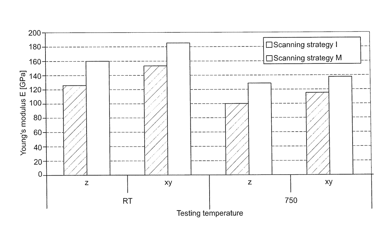
[0066]It has turned out that the mechanical properties along the z-direction are different to ones in the x-y plane, which is the powder plane. The Young's modulus along the z-direction (built direction) is generally lower than the Young's modulus in the x-y plane. This is shown in FIG. 6 for specimens made of Hastalloy® X by additive manufacturing with two different scanning strategies, that means two different scanning patterns, and which were tested at room temperature RT and at a temperature of 750° C. The Young's modulus was measured in the “as built” condition. Due to powder-based article production and the inherent high cooling rates of the energy beam-material interaction in these processes, the material is very homogeneous with respect to chemical composition and...


PUM

PropertyMeasurementUnit
angleaaaaaaaaaa
angleaaaaaaaaaa
Temperatureaaaaaaaaaa

Abstract

The invention refers to a method for manufacturing a hybrid component including the following steps of manufacturing a preform as a first part of the hybrid component, then successively building up on that preform a second part of the component from a metallic powder material by means of an additive manufacturing process by scanning with an energy beam, thereby establishing a controlled grain orientation in primary and in secondary direction of at least a part of the second part of the component. The controlled secondary grain orientation is realized by applying a specific scanning pattern of the energy beam, which is aligned to the cross section profile of the component or to the local load conditions for the component.

Description

CROSS-REFERENCE TO RELATED APPLICATIONS[0001]This application claims priority to European application 13157266.1 filed Feb. 28, 2013, the contents of which are hereby incorporated in its entirety.TECHNICAL FIELD[0002]The present invention relates to the technology of high-temperature resistant components, especially hot gas path components for gas turbines. It refers to a method for manufacturing a hybrid component, preferably a metallic hybrid component, by a combination of laser additive manufacturing, such as selective laser melting (SLM), selective laser sintering (SLS) or electron beam melting (EBM) with conventional manufacturing technologies.BACKGROUND[0003]Additive manufacturing has become a more and more attractive solution for the manufacturing of metallic functional prototypes and components. It is known that SLM, SLS and EBM methods use powder material as base material. The component or article is generated directly from a powder bed. Other additive manufacturing methods...

Claims


Application Information

Patent Timeline
Patent Type & Authority Patents(United States)
IPC IPC(8): B22F3/105B23K26/00B22F5/00B22F7/06B23P6/00B23P15/04B29C67/00
CPCB23K26/0093B22F3/1055B22F5/009B22F7/06B23P6/007B23P15/04B29C64/393Y02P10/295Y10T428/31678Y02P10/25B22F10/28B22F10/366B22F12/90B22F10/38B22F10/64B22F3/105B22F7/00B23K26/08
Inventor HOEBEL, MATTHIASETTER, THOMASKONTER, MAXIMSCHURB, JULIUS
Owner ANSALDO ENERGIA IP UK LTD
Learn More