Arrangement, system, and method of interrupting current

a technology of interrupting current and power system, applied in the direction of emergency protection arrangements for automatic disconnection, air-break switches, electrical equipment, etc., can solve the problems of difficult to achieve optimal switching behavior, less appropriate solution for high-voltage applications, and basically excited oscillating current. to achieve the effect of improving the ability of current interrupting

Active Publication Date: 2019-01-10
SCIBREAK
View PDF5 Cites 19 Cited by
  • Summary
  • Abstract
  • Description
  • Claims
  • Application Information

AI Technical Summary

Benefits of technology

[0014]An object of the present invention is to overcome the problems and drawbacks of the prior art and disclose an improved current interrupting capability regardless of the type of current to be interrupted. Specifically the invention has been designed such that it can successfully handle late voltage breakdown situations, so that a secure current interruption can be ensured.
[0026]In a preferred embodiment, the main branch further comprises a saturable reactor arranged in series with the mechanical breaker to help reduce the rate of change of current in the proximity of the zero cross-over of the current through the mechanical breaker.
[0027]In a preferred embodiment, an additional circuit branch is arranged in parallel with the main branch, and the two-pole, said additional circuit branch being provided with a reverse current control means to, during a current interruption, provide an alternative path for reverse current away from the mechanical breaker. The reverse current control means preferably comprises two thyristors arranged in anti-parallel to control current flow through said two thyristors in opposite directions. Furthermore, the main branch preferably comprises a low-voltage semiconductor switch arranged in series with the mechanical breaker, the low-voltage semiconductor being controllable in use to help divert the current from the mechanical breaker to the additional circuit branch.

Problems solved by technology

This arrangement has the drawback that the oscillation current is basically excited by the arc voltage.
This invention has the drawback of very limited controllability and therefore it is difficult to achieve optimal switching behavior.
Furthermore, the solution is less appropriate in high voltage applications, which present constraints on the proposed charging mechanism.
This proposed solution suffers the disadvantage of having two resonant circuits with added complexity of the control for the two switches that connects the resonant circuits.
The discharge was initiated by firing a controlled triggered gap, thereby limiting the duty of the arrangement to single-shot discharge operations.
This phenomenon most often is caused by particle contamination of the breaking chamber.
However, this circuit topology has shown to be less useful in arrangements for current interruption, that shall effectively handle late voltage breakdown situations as described above.

Method used


Image

  • Arrangement, system, and method of interrupting current
  • Arrangement, system, and method of interrupting current
  • Arrangement, system, and method of interrupting current

Examples


Embodiment Construction

[0060]In the following, a detailed description of an arrangement, a system, and a method for interrupting current according to the invention will be given.

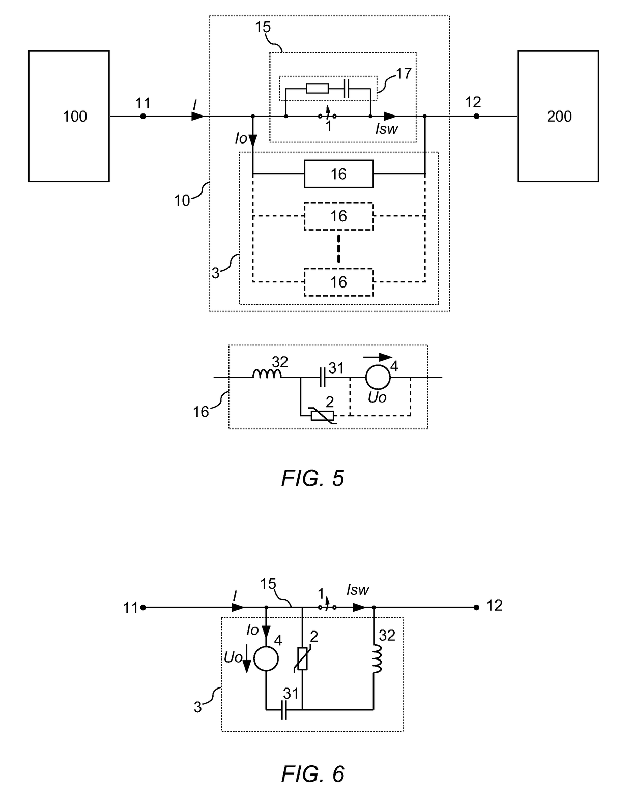
[0061]FIG. 5 shows an overview of the circuit related to the invention. The electrical connection between sections 100, 200 in a power system serves the purpose of transferring electrical power between said sections, in which case a main current I flows through the mechanical breaker 1. The sections 100, 200 may be subsystems of a common power system or separate electrical power transmission systems using dc or ac. Alternatively, the sections may represent an electrical power system feeding a load, e.g. a motor 200 connected to a power source 100.

[0062]At contact separation in the mechanical breaker 1 an internal arc will be established between the contacts and the main current I will continue to flow through the arc. If the mechanical switch operates at high voltage, the arc will only extinguish if a current zero cross-over, natu...


PUM


Abstract

An arrangement for interrupting current comprising a first and a second terminal adapted to electrically connect two sections of a power system is provided. A voltage control means is controllable in use to inject energy into said loop to force a rapid increase of an alternating current flowing through said main branch while being controlled to open to interrupt a main current, and whereby zero cross-over of the current through the mechanical main circuit breaker is realized as the amplitude of the alternating current exceeds the amplitude of the main current. An energy absorbing device is adapted to limit the voltage across said capacitor and said mechanical breaker when the mechanical breaker is open, and across an inductive element if the voltage across the mechanical breaker breaks down, at or immediately after an opening process, thereby limiting the rate-of-rise and the peak of the current through said loop.

Description

[0001]This application is the continuation of International Application No. PCT / SE2016 / 051233, filed 8 Dec. 2016, which claims the benefit of Swedish Patent Application No. SE 1551717-0, filed 28 Dec. 2015, the entire contents of which are hereby incorporated by reference.TECHNICAL FIELD[0002]The present invention relates generally to interrupting current in power systems, and particularly relates to circuit breakers employing an added auxiliary oscillating current to interrupt the main current. The present invention also relates to a system and a method of interrupting current.BACKGROUND ART[0003]The use of circuit breakers or other current interruption means is well established in electrical systems in general, such as in electrical power distribution or transmission systems, especially as a means to protect, isolate and / or control the operation of different components in the power system particularly under fault conditions e.g. short circuit faults, or over-current conditions etc...

Claims


Application Information

Patent Timeline
Patent Type & Authority Applications(United States)
IPC IPC(8): H02H3/02H02H3/087H02H3/08H01H33/59
CPCH02H3/021H02H3/087H01H33/596H01H33/59H02H3/08H01H9/54H01H2009/543
Inventor NORRGA, STAFFANANGQUIST, LENNARTMODEER, TOMAS
Owner SCIBREAK
Why Eureka
Try Eureka