System for liquefying a gas

Active Publication Date: 2019-02-21
CRYOSTAR
View PDF3 Cites 4 Cited by
  • Summary
  • Abstract
  • Description
  • Claims
  • Application Information

AI Technical Summary

Benefits of technology

[0013]Still another object of the invention is to provide a design for gas liquefying systems which is up- or down-scalable, for easily matching liquefact

Problems solved by technology

However such solid piston gas compressors have drawbacks which lead in particular to overh

Method used


Image

  • System for liquefying a gas
  • System for liquefying a gas
  • System for liquefying a gas

Examples


Embodiment Construction

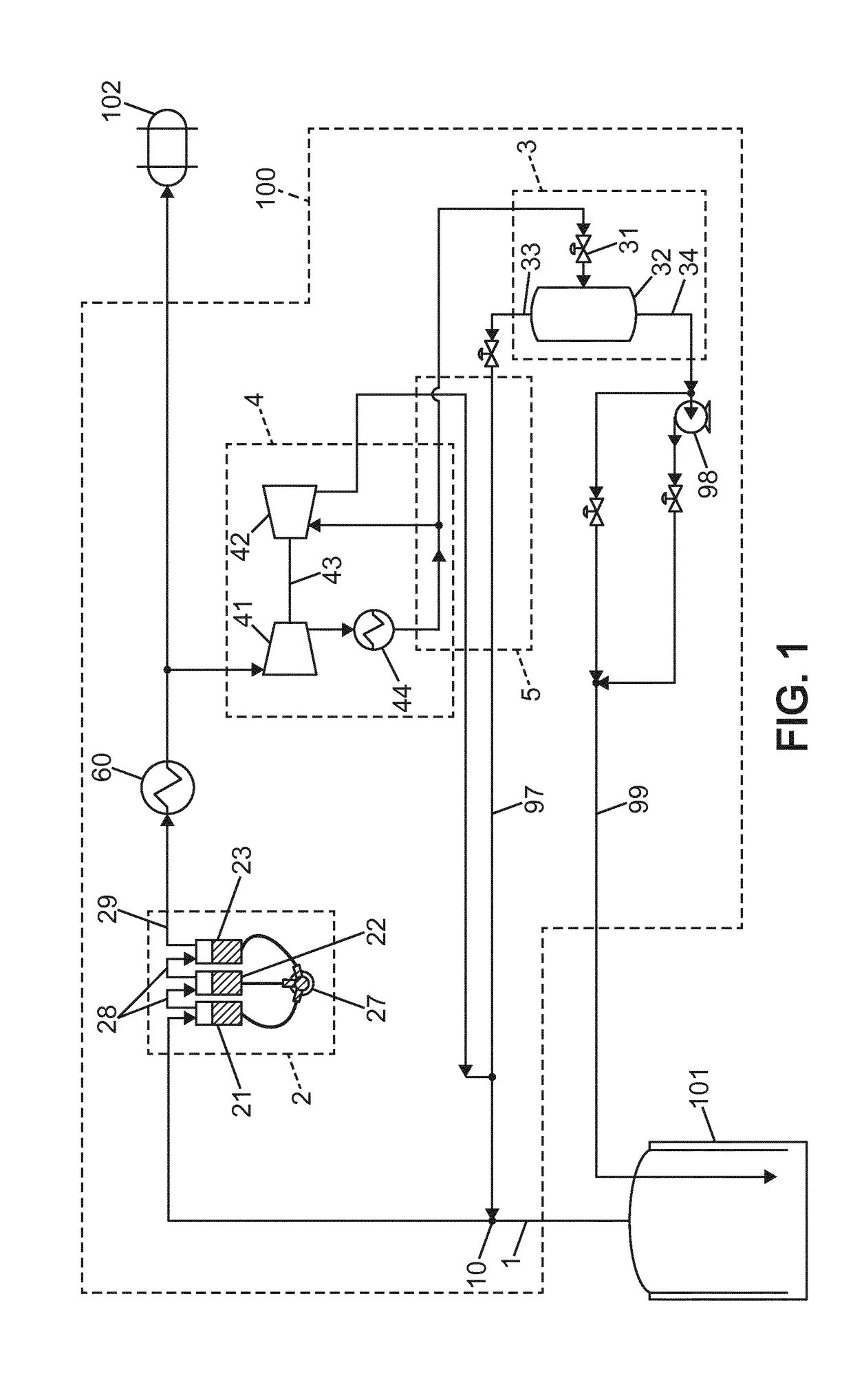
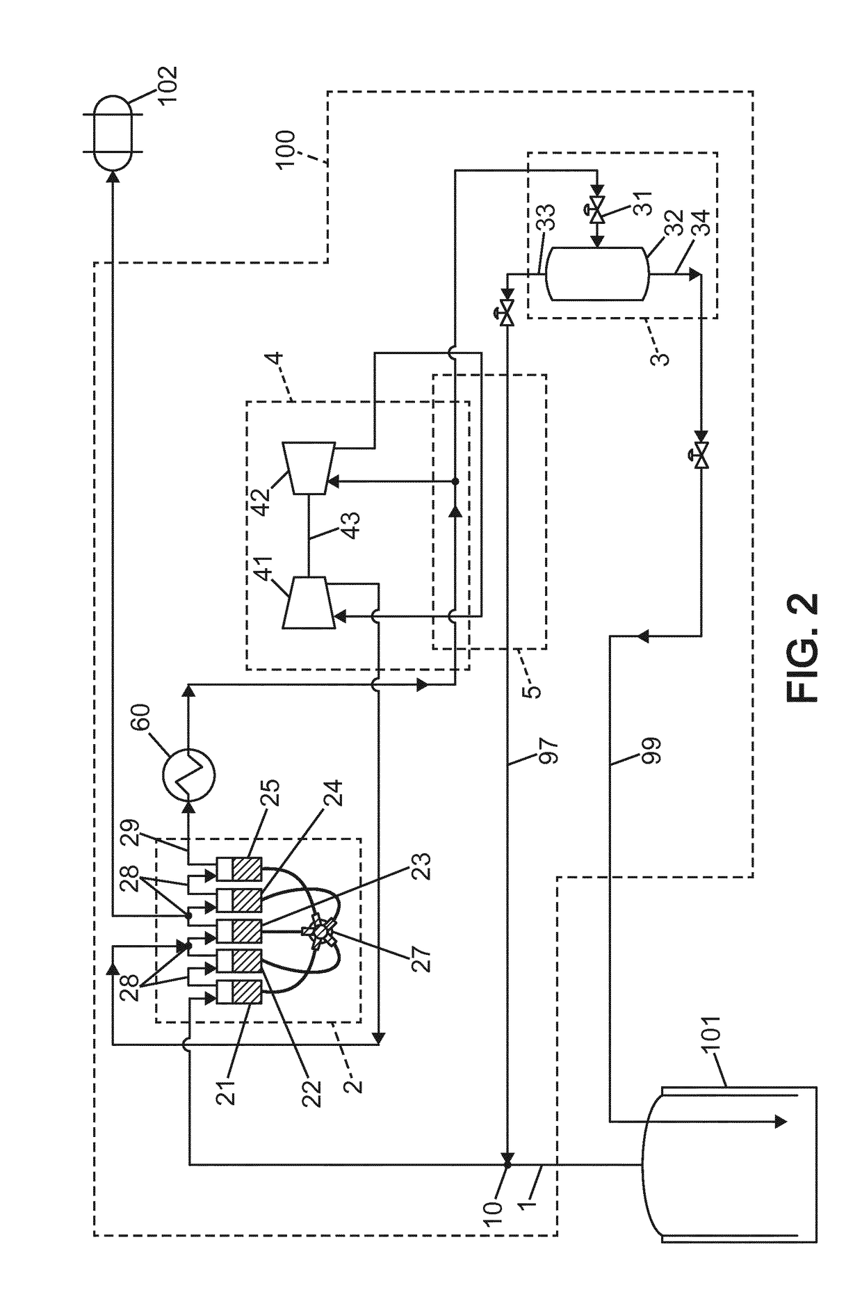
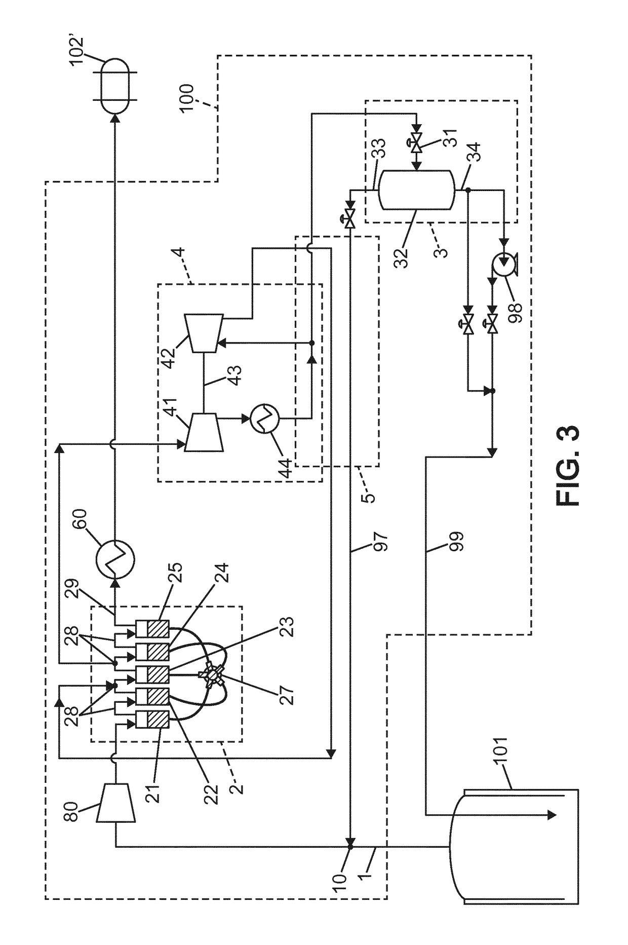
[0030]The invention is now described in detail for several embodiment examples, but without inducing any limitation with respect to the claim scope. In particular, natural gas processing and application to liquefied natural gas carrier vessels will be described, but other gases and applications are encompassed as well by the claims, with identical implementation features or gas-adapted and / or application-adapted implementation features.

[0031]In the figures, the following reference numbers have the meanings now listed:

[0032]100 gas liquefying system

[0033]101 gas source

[0034]102, 102′ gas-fuelled or hybrid fuel vessel propulsion engines

[0035]1 gas intake of the gas liquefying system

[0036]10 duct node

[0037]2 liquid piston gas multistage compressor

[0038]21-23 or 21-25 three or five compressor stages of the liquid piston gas multistage compressor, numbers three and five being only for illustration purpose

[0039]27 source of high-pressure driving liquid

[0040]28 intermediate gas ducts of th...


PUM


Abstract

A system (100) for liquefying a gas comprises a liquid piston gas multistage compressor (2). It can be arranged on-board a liquefied gas carrier for recycling boil-off gas. Such system may be easily adapted or controlled for matching wide requirement ranges for variations of the liquefaction capacity. In addition, at least part of the liquid piston gas multistage compressor can be shared between the gas liquefying system and an extra gas-fed device. Such extra gas-fed device may be in particular a gas-fuelled or hybrid fuel propulsion engine of the vessel.

Description

[0001]The invention relates to a system for liquefying a gas. It also relates to a liquefied gas carrier which is equipped with such system.BACKGROUND OF THE INVENTION[0002]Gas liquefying systems have been known for long time. Such system comprises:[0003]a gas intake for connection to a gas source;[0004]at least one gas compressor;[0005]a gas expansion device, which is connected for being fed with compressed gas produced by the at least one gas compressor, and adapted to produce both liquefied gas and expanded gas from the compressed gas; and[0006]a return duct which is connected for driving the expanded gas from a gas outlet of the gas expansion device to a duct node situated between the gas intake and the at least one compressor.[0007]Hence such system is provided with a loop-path for the gas, such that part of the gas which has not been converted into liquid upon running only once through the gas expansion device, namely the expanded gas discharged by the gas expansion device, is...

Claims


Application Information

Patent Timeline
IPC IPC(8): F25J1/00F25J1/02
CPCF25J1/0025F25J1/0202F25J1/004F25J1/023F25J1/0277F25J1/0288F25J1/0292F25J1/0294F25J1/0296F25J1/0037F25J1/0279
Inventor RAGOT, MATHIASMARCUCCILLI, FREDERIC
Owner CRYOSTAR
Why Eureka
Try Eureka