Supercharge Your Innovation With Domain-Expert AI Agents!

Leading edge structure

a leading edge and skin structure technology, applied in the direction of wings, spars/stringers, wings, etc., can solve the problems of buckling on the leading edge skin surface, panels that do not generally carry the main wing load, and the same problems apply, so as to reduce the unsupported panel size of the skin structure, prevent buckling, and reduce the weight of the leading edge structure

Active Publication Date: 2019-03-28
AIRBUS OPERATIONS LTD +1
View PDF0 Cites 1 Cited by
  • Summary
  • Abstract
  • Description
  • Claims
  • Application Information

AI Technical Summary

Benefits of technology

[0016]Having structural members integrally formed with the inner surface of the skin structure means that a separate fastening does not have to be used to attach the structural members to the skin structure. This means that, for example, there are fewer rivets through the skin structure and therefore fewer corresponding bumps on the outer aerodynamic surface of the leading edge structure skin. This encourages laminar flow over the leading edge structure.
[0072]Preferably, the strut has an adjustable length. This allows the skin structure to be connected to the sub-structure in an adjustable way in order to achieve and maintain the optimum waviness.

Problems solved by technology

It should be noted that the some of the same problems apply to other leading edge structures that are part of a structural member of an aircraft, but not part of a wing structure.
These panels do not generally carry the main wing loads and, instead, simply maintain the aerodynamic shape.
This provides bumps on the leading edge skin surface, which have a negative effect on laminar flow.

Method used


Image

  • Leading edge structure
  • Leading edge structure
  • Leading edge structure

Examples


first embodiment

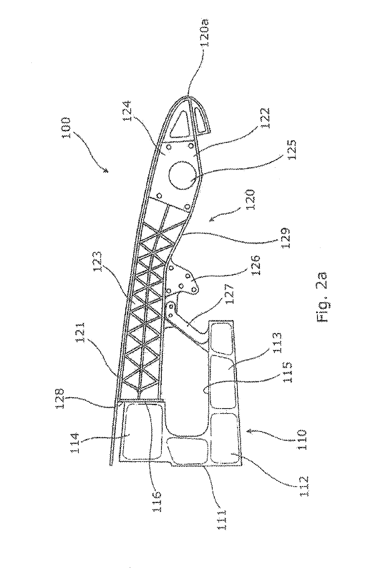
[0092]FIG. 2a shows a view of part of a wing structure 100, including a wing box structure 110 and a leading edge structure 120, according to the first aspect of the invention.

[0093]The wing box structure 110 comprises a front main spar 111 with a machined fitting 112 attached to it. The machined fitting 112 has two forwardly extending portions 113, 114. The first, lower forwardly extending portion 113 extends from the bottom of the spar 111. The second, upper forwardly extending portion 114 extends from the top of the spar 111.

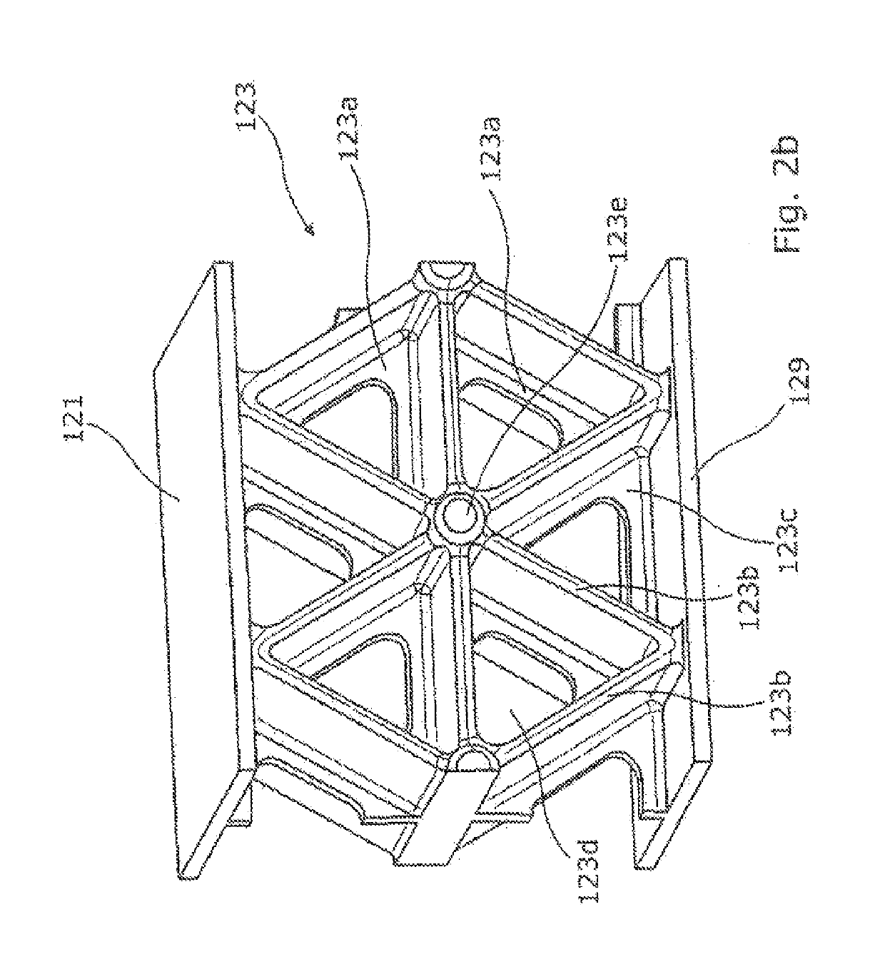
[0094]The leading edge structure 120 comprises an upper skin 121 which forms the front nose 120a of the wing. Underneath the upper 121 are various ribs (one, 122, shown). Each rib 122 is integrally formed with the upper skin 121 and has a lower stiffening flange 129. In addition, the upper skin 121 is provided with integral stiffeners / varied thickness (not shown).

[0095]Each rib 122 has a front portion 124 near the nose 120a, which is a solid portion, with var...

second embodiment

[0103]FIGS. 3a and 3b show views of part of a leading edge 120′ skin structure 121′, according to the first aspect of the invention.

[0104]The skin structure 121′ comprises various flanges 130a′, 130b′ extending in a chordwise direction from the nose 120a′ along the inside of the skin structure 121′. These flanges 130a′, 130b′, 130c′, 130d′ are integrally formed with the skin structure 121′ by casting, for example. During assembly, ribs are mounted on these flanges 130′.

[0105]In addition, the skin structure 121′ has a varying thickness and has a lattice pattern 131′ formed in between each of the flanges 130′ on the inner face of the skin structure 121′. The lattice pattern 131′ comprises triangular cells 131a′ with cell walls 131b′ and riser nodes 131e′.

[0106]As well as casting, the skin structure 121′ can be manufactured as an integral composite component or can be machined from a solid metallic alloy billet.

[0107]FIGS. 4a and 4b show views of part of a leading edge structure 220 a...


PUM


Abstract

A leading edge structure for providing an aerodynamic surface of an aircraft is disclosed having a skin structure, the skin structure providing an outer aerodynamic surface and an inner surface, both surfaces extending in a chordwise and spanwise direction of the structure, and a plurality of structural members, each structural member being connected to the inner surface of the skin structure and extending in the chordwise direction along the inner surface, wherein the structural members are integrally formed with the inner surface of the skin structure. The disclosure is also related to an aircraft wing, aircraft tailplane, wing box structure, wing or wing structure and an aircraft including the leading edge structure.

Description

CROSS RELATED APPLICATIONS[0001]This application is a Divisional of U.S. patent application Ser. No. 14 / 360,512, filed May 23, 2014, now pending, which is the U.S. National Phase of International Application No. PCT / GB2012 / 052888, filed Nov. 22, 2012, and claims priority from United Kingdom (GB) Patent Application No. 1120707.3, filed Dec. 1, 2011, the entire contents of which are hereby incorporated by reference.BACKGROUND OF THE INVENTION[0002]The present invention concerns a leading edge structure. More particularly, but not exclusively, this invention concerns a leading edge structure for providing an aerodynamic surface of an aircraft, the leading edge structure comprising a skin structure and a plurality of ribs and / or sub-spars for supporting the skin structure.[0003]In aircraft wing design, it is important to design the wings such that flow over the wings stays laminar for as long as possible. This requires the leading edge structure of the wing to be designed and manufactur...

Claims


Application Information

Patent Timeline
Patent Type & Authority Applications(United States)
IPC IPC(8): B64C3/28B64C3/00B64C3/18B64C3/24B64C3/14
CPCB64C3/28B64C3/00B64C2003/146B64C3/24B64C3/18B64C3/187
Inventor WILLIAMS, LLIFONSALISBURY, ROSSRAFLA, MARCUSTHEOBALD, HUGHPAYNE, CHRISTOPHERMCCORMICK, ROBERTHANSEN, HEINZEVANS, TIMOTHY
Owner AIRBUS OPERATIONS LTD
Features
  • R&D
  • Intellectual Property
  • Life Sciences
  • Materials
  • Tech Scout
  • Unparalleled Data Quality
  • Higher Quality Content
  • 60% Fewer Hallucinations
Learn More