Customizable instrument

a technology of custom instruments and instruments, applied in the field of custom instruments, can solve the problems of inefficiency and slowness of such systems, and achieve the effect of improving efficiency and reducing labor intensity

a technology of custom instruments and instruments, applied in the field of custom instruments, can solve the problems of inefficiency and slowness of such systems, and achieve the effect of improving efficiency and reducing labor intensity

US20190101542A1Active Publication Date: 2019-04-04HYCOR BIOMEDICAL LLC

Image

  • Customizable instrument
  • Customizable instrument
  • Customizable instrument

Examples


Embodiment Construction

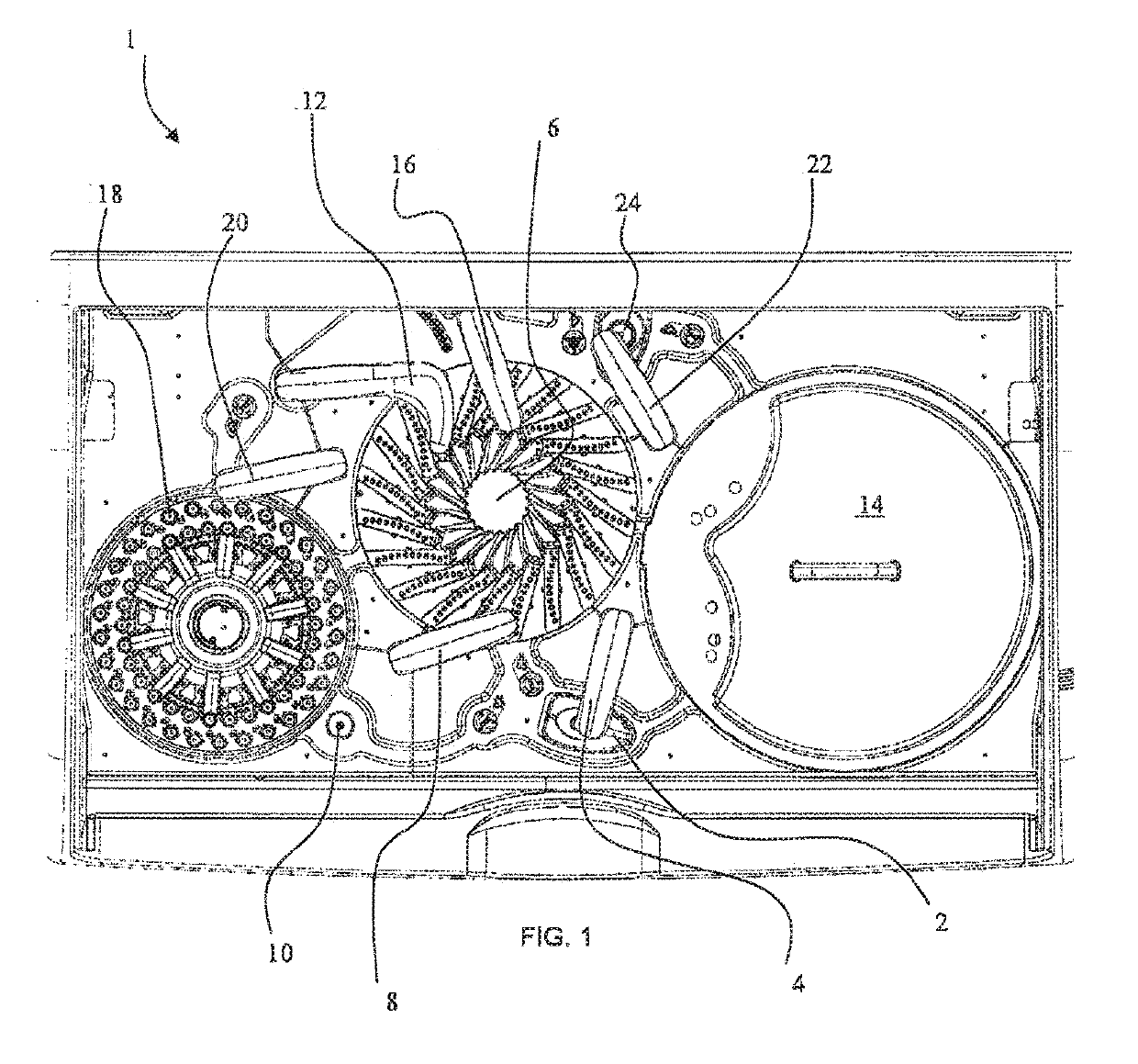
[0021]Before describing in detail the illustrative system and method of the present disclosure, it should be understood and appreciated herein that the present disclosure relates to methods and apparatus that mix a plurality of individual capture reagents to optimize diagnostic assays for different types of analyte molecules of interest. In general, the system utilizes common paramagnetic particles, for example, magnetic beads or microparticles that are pulled to the wall of a reaction cuvette by magnets during a washing process so that liquid can be aspirated from the cuvette.

[0022]In some embodiments, the present systems are not microfluidics systems which may include DNA chips, lab-on-a-chip technology, micro-propulsion, and micro-thermal technologies. In some embodiments, the present systems include immunoanalyzer instruments that can use one or more automated pipettor, reaction rotors, physically picking up and moving samples and reagents, and combinations thereof.

[0023]In the ...


PUM

PropertyMeasurementUnit
paramagneticaaaaaaaaaa
optical analysisaaaaaaaaaa
luminescentaaaaaaaaaa

Abstract

Methods and apparatus that mix a plurality of individual capture reagents for the diagnostic assays are described herein. In an embodiment, a system for optically analyzing a patient sample includes an automated immunochemistry analyzer storing a plurality of capture reagents and a plurality of paramagnetic particles, a user interface configured to allow a selection of a combination of two or more of the capture reagents, and a logic implementer configured to cause the automated immunochemistry analyzer to (i) mix together each capture reagent of the combination of two or more of the capture reagents; (ii) bind the mixture of the combination of two or more of the capture reagents to the paramagnetic particles; (iii) bind the patient sample to the bound mixture of the combination of two or more of the capture reagents; and (iv) optically analyze the patient sample.

Description

CROSS REFERENCE TO RELATED APPLICATIONS[0001]This application claims priority to U.S. Provisional Application Ser. No. 62 / 214,740, filed Sep. 4, 2015 and U.S. Provisional Application Ser. No. 62 / 192,989, filed Jul. 15, 2015, the entire disclosure each of which is hereby incorporated.FIELD OF THE DISCLOSURE[0002]The present disclosure relates generally to methods and apparatuses for performing diagnostic assays, and more specifically to methods and apparatus that mix a plurality of individual capture reagents for the diagnostic assays.BACKGROUND OF THE DISCLOSURE[0003]Many immunochemistry analysis systems require that analyte molecules in a patient's biological sample (e.g. serum or plasma) attach to paramagnetic particles. To bind analyte molecules of interest to the paramagnetic particles, a capture reagent is first bound to the paramagnetic particles, and then the patient sample is bound to the capture reagent. The analyses performed by such systems, however, are relatively slow a...

Claims


Application Information

Patent Timeline
04 Apr 2019
Publication
US20190101542A1
IPC
G01N33/58; G01N35/00; G01N21/64
CPC
G01N33/582; G01N35/00871; G01N35/0098; G01N21/6428; G01N35/0092; G01N2035/00564; G01N2035/00881; G01N2035/0091
Inventors
VAN CLEVE, MARK DAVID; TAINE, ELAINE GRACE