Tactile sensation providing apparatus and control method for tactile sensation providing apparatus

a technology of tactile sensation and providing apparatus, which is applied in the direction of mechanical pattern conversion, instruments, computing, etc., can solve the problems of operator stress, operator inability to obtain feedback to input, and difficulty in confirming auditory feedback, etc., and achieve the effect of constant tactile sensation

Active Publication Date: 2019-06-13
KYOCERA CORP
View PDF0 Cites 0 Cited by
  • Summary
  • Abstract
  • Description
  • Claims
  • Application Information

AI Technical Summary

Benefits of technology

The present invention is a device that provides a steady touch sensation to users through vibration. It does not rely on the user's position to control the touch, ensuring a consistent experience no matter where the user presses.

Problems solved by technology

Since the touch sensors are not physically displaced when touched, an operator cannot obtain feedback to an input even when the touch input is received.
As a result, the operator is likely to input erroneously by touching the same spot multiple times, which may be stressful for the operator.
However, such auditory feedback may be difficult to be confirmed in a noisy environment and is not applicable when the equipment being used is in a silent mode.
In addition, in using such visual feedback, when the operator is inputting by the finger, if the input object displayed on the display unit is small, the operator may not be able to confirm the change in the display state, as a view of the input object is blocked by a finger.

Method used


Image

  • Tactile sensation providing apparatus and control method for tactile sensation providing apparatus
  • Tactile sensation providing apparatus and control method for tactile sensation providing apparatus
  • Tactile sensation providing apparatus and control method for tactile sensation providing apparatus

Examples


first embodiment

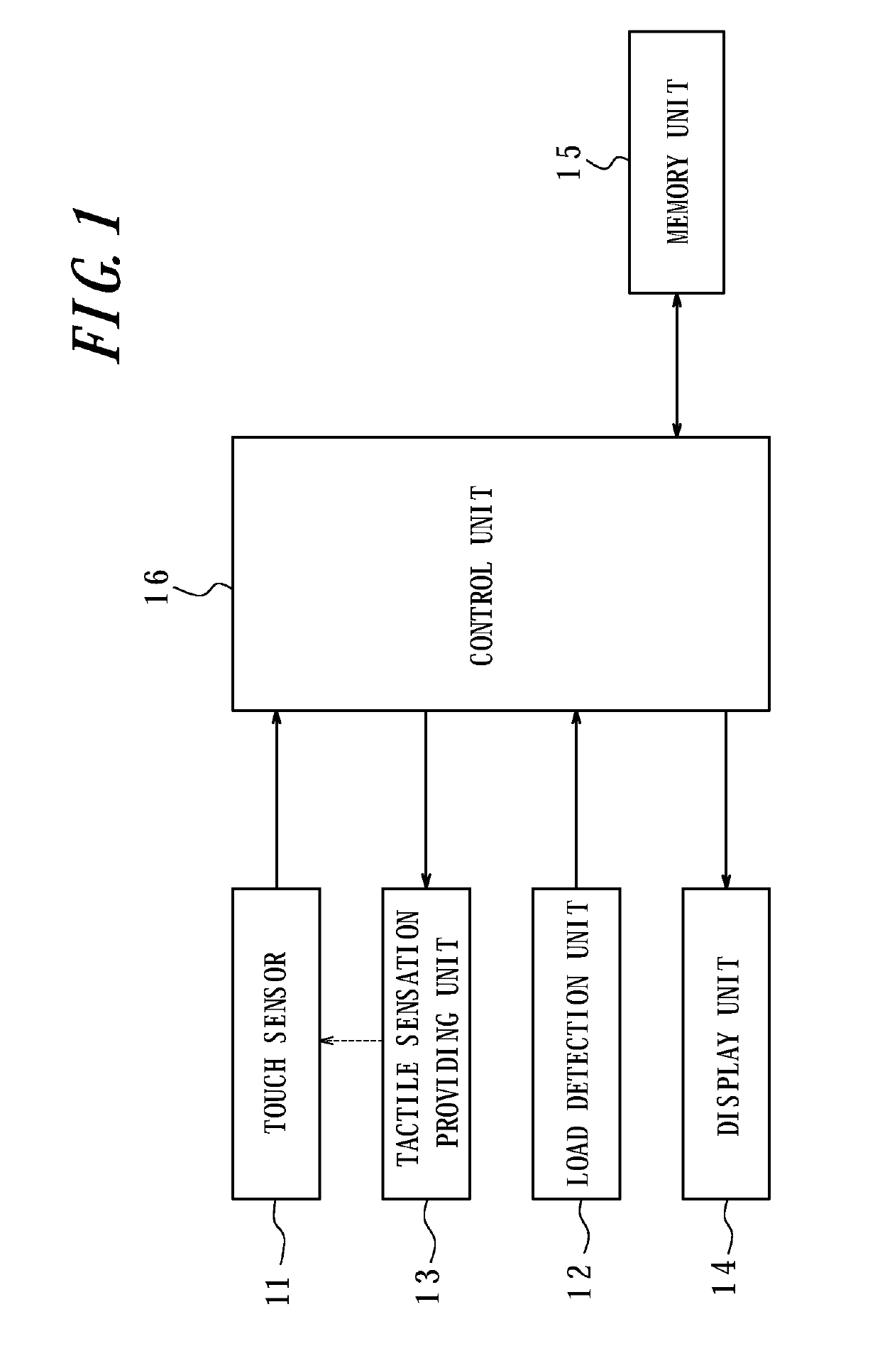
[0040]FIG. 1 is a functional block diagram illustrating a tactile sensation providing apparatus according to a first embodiment of the present disclosure. This tactile sensation providing apparatus has a touch sensor 11, a load detection unit 12, a tactile sensation providing unit 13, a display unit 14, a memory unit 15, and a control unit 16 to control overall operations.

[0041]The touch sensor 11, disposed on the display unit 14, detects a touch input to a touch face by a touch object such as a finger and the like and may be of a known type, such as a resistive film type, a capacitive type, an optical type and the like to output two-dimensional position information of a touch position (pushed position of a pressing object such as the finger and the like). The load detection unit 12 detects a pressure load on the touch face of the touch sensor 11 by the pressing object such as the finger and the like and may be, for example, a strain gauge sensor, a piezoelectric element and the lik...

second embodiment

[0067]FIG. 4 is a functional block diagram illustrating a schematic configuration of a tactile sensation providing apparatus according to a second embodiment of the present disclosure. This tactile sensation providing apparatus has a configuration of that according to the first embodiment illustrated in FIG. 1, except for having the piezoelectric element 17 in place of the load detection unit 12 and the tactile sensation providing unit 13. The touch sensor 11, the display unit 14, the memory unit 15 and the control unit 16 have the same functions as those of the first embodiment, and thus detailed descriptions thereof are omitted. According to the present embodiment, the “load detection unit 12” and the “tactile sensation providing unit 13” in the descriptions of the touch sensor 11, the display unit 14, the memory unit 15 and the control unit 16 of the first embodiment are substituted for the “piezoelectric element 17”.

[0068]The piezoelectric element 17 is mounted on the touch sens...


PUM


Abstract

A tactile sensation providing apparatus includes a touch sensor configured to detect a touch input, a load detection unit configured to detect a pressure load on a touch face of the touch sensor, a tactile sensation providing unit configured to vibrate the touch face, and a control unit configured to adjust a drive signal of the tactile sensation providing unit based on a pushed position when the pressure load detected by the load detection unit satisfies a standard to provide a tactile sensation.

Description

CROSS-REFERENCE TO RELATED APPLICATIONS[0001]This application is a Continuation Application of U.S. patent application Ser. No. 13 / 392,855, filed Feb. 27, 2012, which is the U.S. National Phase of International Application No. PCT / JP2010 / 005186 filed Aug. 23, 2010, which claims priority to and the benefit of Japanese Patent Application No. 2009-197444 filed Aug. 27, 2009 and Japanese Patent Application No. 2010-149063 filed Jun. 30, 2010, the entire contents of which are incorporated herein by reference.TECHNICAL FIELD[0002]The present disclosure relates to a tactile sensation providing apparatus having a touch sensor and a control method for a tactile sensation providing apparatus.BACKGROUND ART[0003]In recent years, input apparatuses having touch sensors such as touch panels, touch switches or the like are popularly used as input apparatuses such as operation units, switches and the like for receiving input operations by a user in mobile terminals such as mobile phones, gaming mac...

Claims


Application Information

Patent Timeline
Patent Type & Authority Applications(United States)
IPC IPC(8): G06F3/01G06F3/041
CPCG06F3/016G06F3/041G06F2203/04105G06F3/0416G06F3/04142H10N30/20
Inventor KUWABARA, MEGUMIKONO, KENJIAONO, TOMOTAKETAKEDA, JUN
Owner KYOCERA CORP
Why Eureka
Try Eureka