Tactile sensation presenting device

Inactive Publication Date: 2019-11-07
ALPS ALPINE CO LTD
View PDF3 Cites 1 Cited by
  • Summary
  • Abstract
  • Description
  • Claims
  • Application Information

AI Technical Summary

Benefits of technology

[0022]Thereby, because a load level actually applied can be detected, the noise resistance is excellent when detecting pressure. Further, because of a simple configuration, implementation is easy.
[0023]According to an aspect of the present in

Problems solved by technology

Therefore, it is difficult to realistical

Method used


Image

  • Tactile sensation presenting device
  • Tactile sensation presenting device
  • Tactile sensation presenting device

Examples


first embodiment

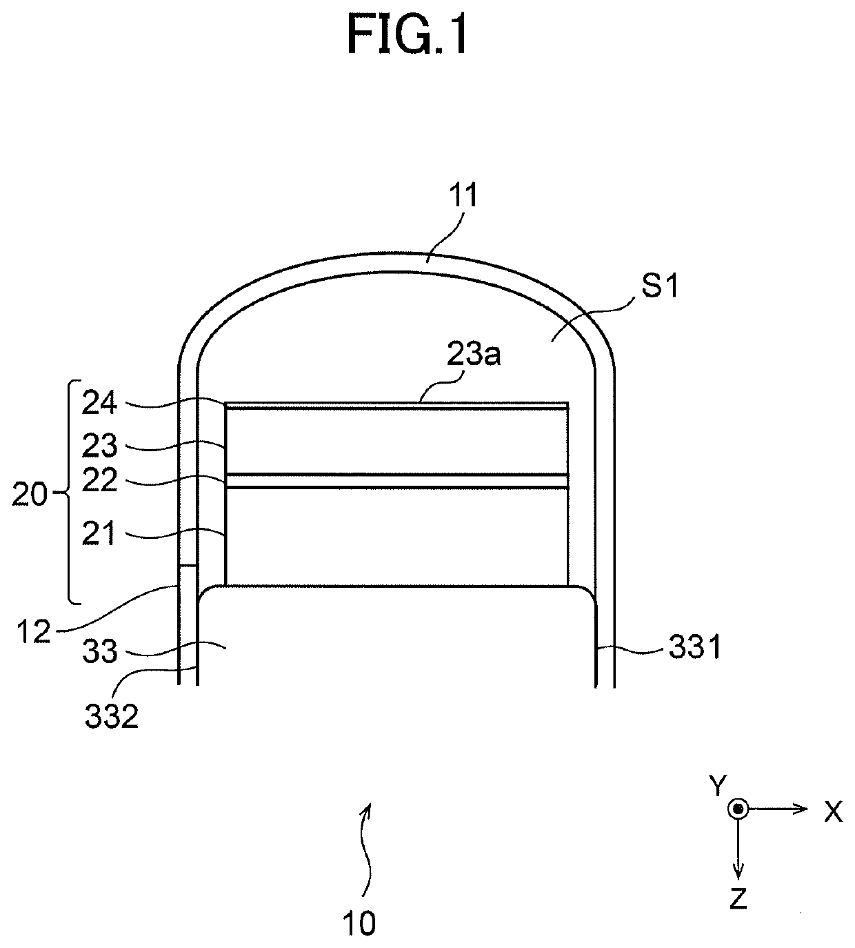
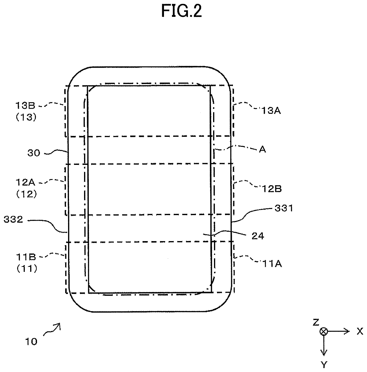
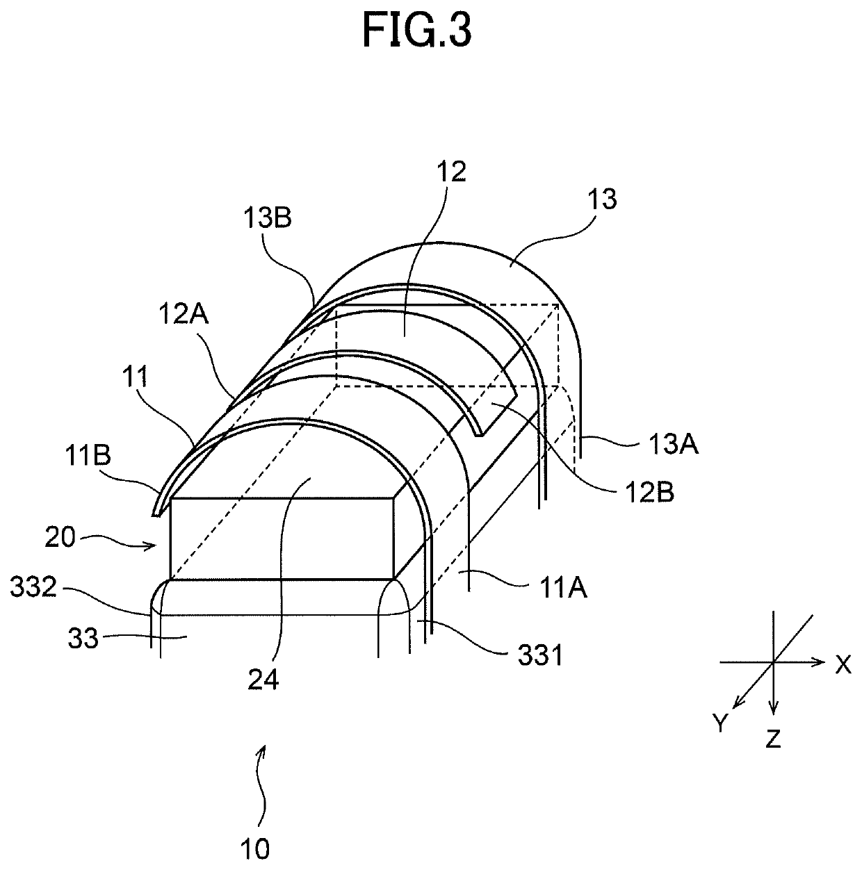
[0036]FIG. 1 is a side view illustrating a schematic configuration of a tactile sensation presenting device 10 according to a first embodiment; FIG. 2 is a plan view of the tactile sensation presenting device 10 that is illustrated in FIG. 1; FIG. 3 is a perspective view illustrating the tactile sensation presenting device 10 illustrated in FIG. 1 as seen from above; FIG. 4 is a side view when a finger F is in contact with a pressure detecting unit 24; and FIG. 5 is a functional block diagram of the tactile sensation presenting device 10. In FIG. 1 to FIG. 4, X-Y-Z coordinates are illustrated as reference coordinates. In the following description, a state viewed from the upper side to the lower side in the Z direction may be referred to as plan view, and the Z direction is a direction perpendicular to an X-Y plane. In FIG. 2, for the sake of description, holding members 11, 12, and 13 are illustrated by dashed lines.

[0037]The tactile sensation presenting device 10, as illustrated in...

second embodiment

[0062]FIG. 6 is a diagram illustrating an example of first use of an input device 40 and a display device 51A according to a second embodiment, and FIG. 7 is a diagram illustrating an example of second use of input devices 40 and a display device 51B. FIG. 8A and FIG. 8B are perspective views illustrating a configuration of the input device 40 illustrated in FIG. 6 and FIG. 7. FIG. 8A is a diagram illustrating the input device 40 as viewed from above, and FIG. 8B is a diagram illustrating the input device 40 as viewed from below. FIG. 9 is an exploded perspective view illustrating a configuration of a tactile sensation presenting device 10A in the input device 40 illustrated in FIGS. 6 to 8. FIG. 10 is a functional block diagram of the tactile sensation presenting device 10A.

[0063]In the first use illustrated in FIG. 6, one input device 40 and the display device 51A are connected to each other by a code 40A and the input device 40 is operated by an operator's right hand. The display...


PUM


Abstract

A tactile sensation presenting device includes: a vibrating element configured to present vibration information; a warmth/coldness presenting element provided above the vibrating element and configured to present warm/cold information to a tactile sensation presentation surface; a pressure detecting unit configured to detect a pressure corresponding to a contact state of an operating part with respect to the tactile sensation presentation surface; and an adjusting unit configured to adjust a presentation condition based on a detection result by the pressure detecting unit.

Description

CROSS-REFERENCE TO RELATED APPLICATIONS[0001]This application is a continuation of International Application No. PCT / JP2018 / 002019, filed on Jan. 23, 2018 and designated the U.S., which claims priority to Japanese Patent Application 2017-019196, filed on Feb. 6, 2017. The contents of these applications are incorporated herein by reference in their entirety.BACKGROUND OF THE INVENTION1. Field of the Invention[0002]The present invention relates to a tactile sensation presenting device for presenting warm / cold information and vibration information when touched by an operating part such as a finger.2. Description of the Related Art[0003]Patent Document 1 describes a device in which a tactile sensation presenting device that generates vibration by a voice coil, a piezoelectric element, or the like, a Peltier element that presents a warm sensation, and a sensor that measures a temperature of skin are disposed on a base. The tactile sensation presenting device and the sensor are directly d...

Claims


Application Information

Patent Timeline
IPC IPC(8): G06F3/01G06F3/044G06F3/045
CPCG06F3/044G06F3/016G06F3/045
Inventor SATO, KUNIOTAKAI, DAISUKEKAWANA, YUZURU
Owner ALPS ALPINE CO LTD
Why Eureka
Try Eureka