
Variable power dimming control circuit

Active Publication Date: 2014-10-30
EPISTAR CORP
View PDF9 Cites 55 Cited by
  • Summary
  • Abstract
  • Description
  • Claims
  • Application Information

AI Technical Summary

Benefits of technology

The present invention provides a variable power dimming control circuit that detects the input voltage power and adjusts the brightness of LEDs to improve dimming stability and reduce unnecessary power consumption. The circuit includes a detector, a controller, a current limiter, and a feedback device to compare and adjust the current and driving current to ensure stable operation and reduce heat energy production. The circuit also includes a driving unit and a current transfer component to facilitate the conversion of voltage power and improve overall operating efficiency. The technical effects of the invention include improved dimming stability, reduced power consumption, and enhanced heat dissipation effect.

Problems solved by technology

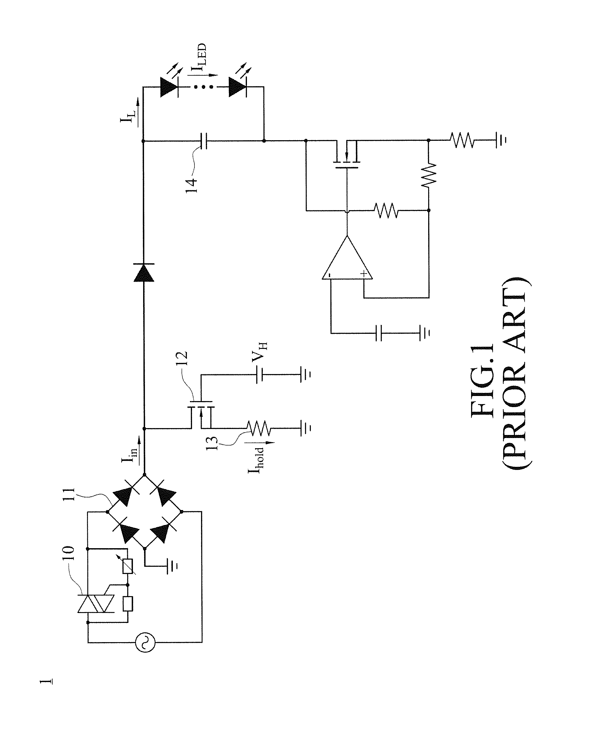
However, the TRIAC is a component that requires a standard operating voltage, so that if the conduction angle of the input power is too small and the overall operating voltage of the circuit has a voltage power smaller than a standard operating voltage required by the TRIAC, the TRIAC will be unable to operate normally, and the operating quality of the driver circuit will be affected adversely.
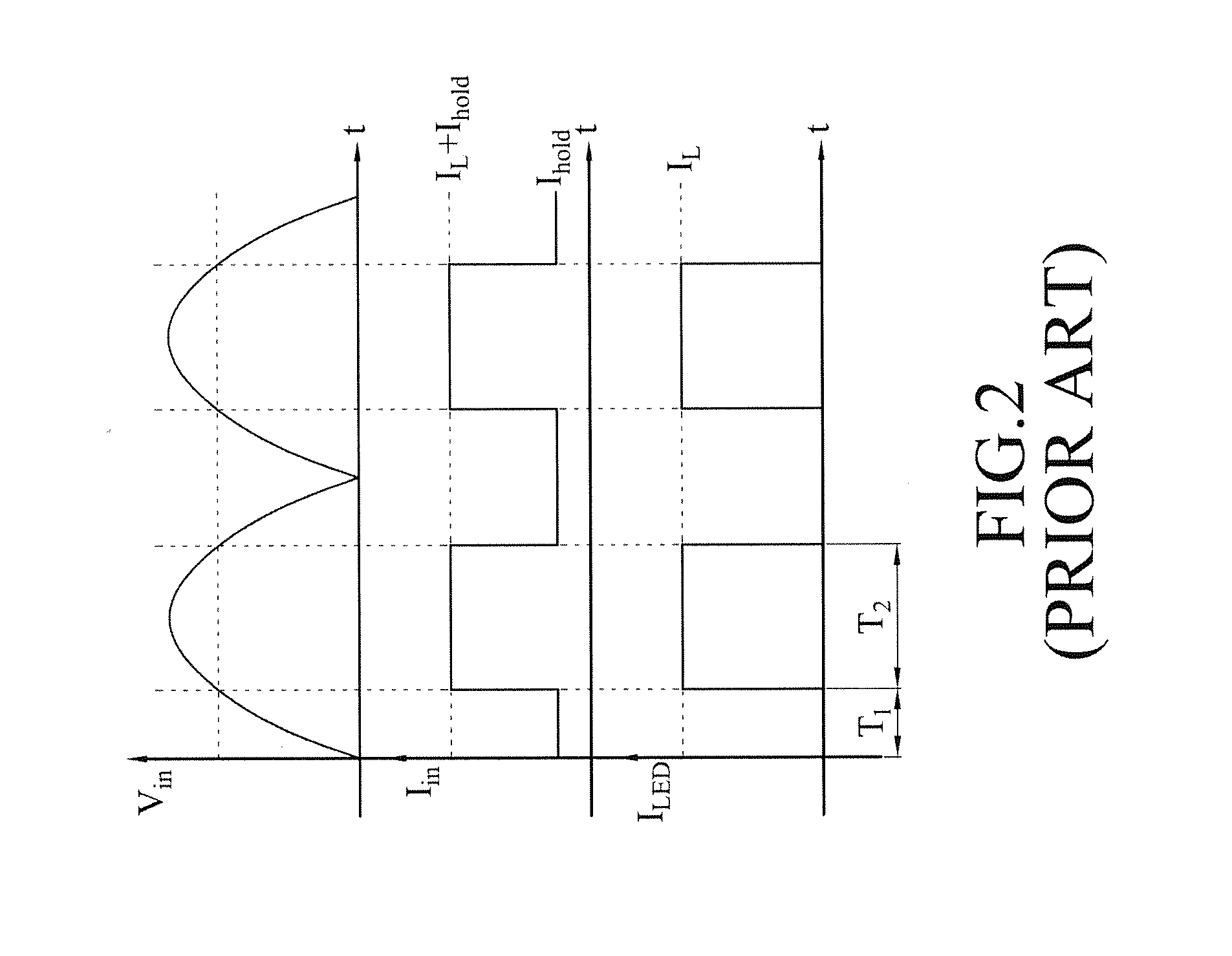
In other words, regardless of the magnitude of the input power of the circuit, the holding current keeps operating, and thus causing the problems of consuming unnecessary power and lowering the power conversion efficiency of the whole circuit.

Method used


Image

  • Variable power dimming control circuit
  • Variable power dimming control circuit
  • Variable power dimming control circuit

Examples


Embodiment Construction

[0021]The technical content of the present invention will become apparent with the detailed description of preferred embodiments and the illustration of related drawings as follows.

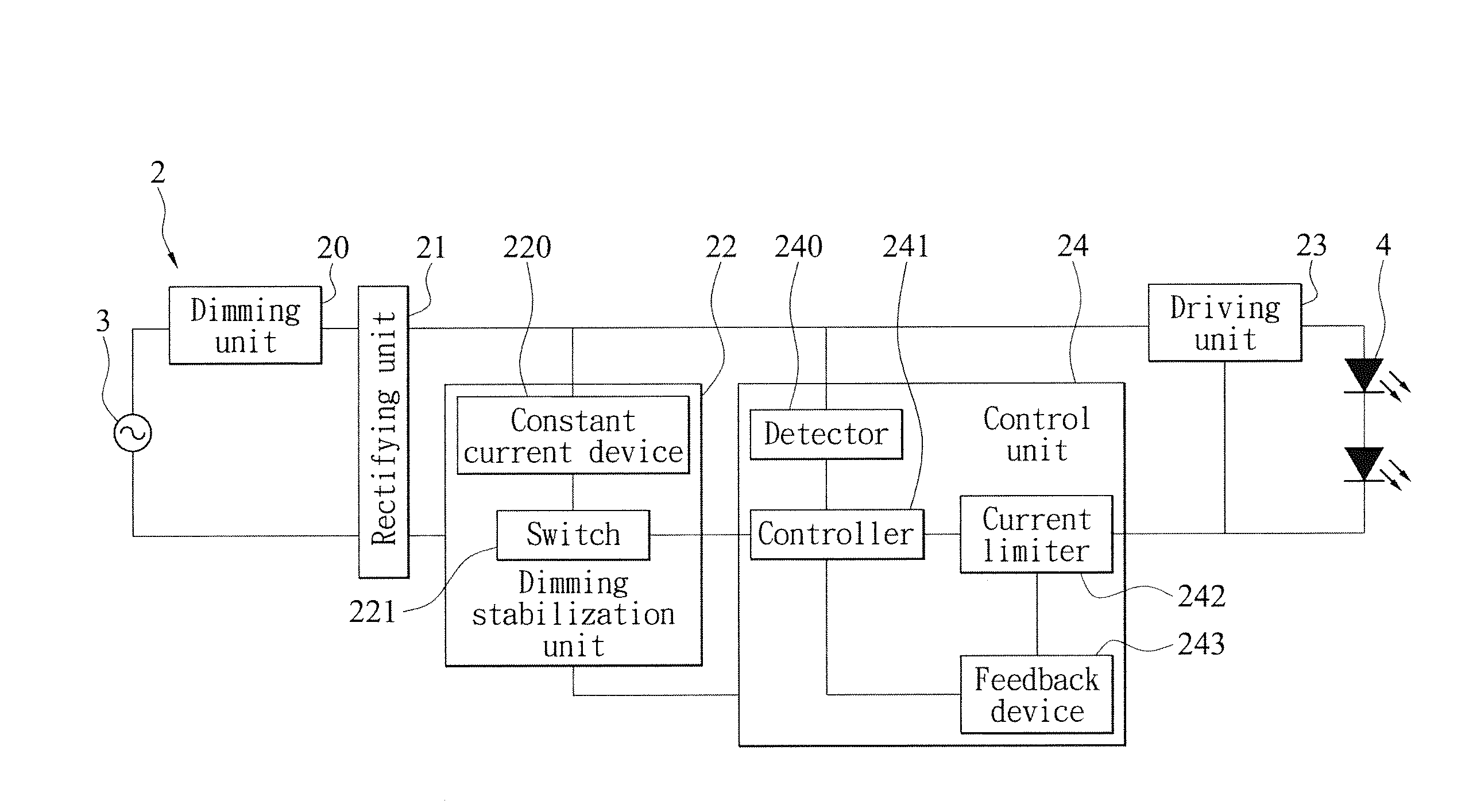
[0022]With reference to FIGS. 3 to 5 for block diagrams of two implementation modes and a circuit diagram of a preferred embodiment of the present invention respectively. As shown in the figures, a variable power dimming control circuit 2 is installed at a light board module (not shown in the figures) of a lamp for converting a voltage power of an external power supply 3 to drive and linearly adjust the illumination brightness of a plurality of LEDs 4, and the LEDs 4 are electrically connected in series or in parallel and installed on the light board module. The variable power dimming control circuit 2 comprises a dimming unit 20, a rectification unit 21, a dimming stabilization unit 22, a driving unit 23 and a control unit 24, and the dimming stabilization unit 22 comprises a constant current device 220 ...


PUM


Abstract

Disclosed is a variable power dimming control circuit for driving and linearly adjusting the illumination brightness of a plurality of light emitting diodes (LEDs), and the circuit includes a dimming stabilization unit and a control unit. The control unit is provided for detecting an input current of a circuit, and the dimming stabilization unit is driven for outputting a holding current when the input power is smaller than a standard, and stopping the output the holding current when the input power is greater than the standard. When the LEDs are dimmed to low luminance, a chip controls the operation of the dimming stabilization unit to assure the stability of the dimming operation of a TRIAC. When the LEDs are adjusted to high or full brightness, the chip stops the output of the holding current to reduce unnecessary power consumption and enhance the overall circuit performance effectively.

Description

CROSS-REFERENCE TO RELATED APPLICATIONS[0001]This non-provisional application claims priority under 35 U.S.C. §119(a) on Patent Application No(s). 102115052 filed in Taiwan, R.O.C. on Apr. 26, 2013, the entire contents of which are hereby incorporated by reference.BACKGROUND OF THE INVENTION[0002]1. Field of the Invention[0003]The present invention relates to the field of light emitting diode (LED) power devices, and more particularly to a variable power dimming control circuit that supports the linear light dimming of a bi-directional TRI-electrode AC (TRIAC) switch and provides a holding current to stabilize the operating quality of the TRIAC switch when the LED is dimmed to a low brightness, and stops supplying the output of the holding current when the brightness of the LED is increased, so as to achieve the effects of reducing unnecessary power consumption of the circuit and minimizing the heat produced during the operation of the LED.[0004]2. Description of the Related Art[000...

Claims


Application Information

Patent Timeline
IPC IPC(8): H05B33/08H05B44/00
CPCH05B33/0845Y02B20/30H05B45/3725H05B45/397H05B45/10
Inventor WU, CHIH-HSIENCHANG, WEILU, HUAN-YINGCHUANG, KAI-CHENGCHIU, SHAO-WEI
Owner EPISTAR CORP
Learn More