Balancer shaft arrangement for engine

Active Publication Date: 2006-02-23
YAMAHA MOTOR CO LTD
View PDF13 Cites 6 Cited by
  • Summary
  • Abstract
  • Description
  • Claims
  • Application Information

AI Technical Summary

Benefits of technology

[0009] By dividing at least one of the balancer weights so as to lie on opposite sides of the corresponding bearing, the bending moment acting on a bearing portion of the balancer shaft can be reduced. The d

Problems solved by technology

Additionally, this construction lessens uneven loadings of the correspon

Method used


Image

  • Balancer shaft arrangement for engine
  • Balancer shaft arrangement for engine
  • Balancer shaft arrangement for engine

Examples


Example

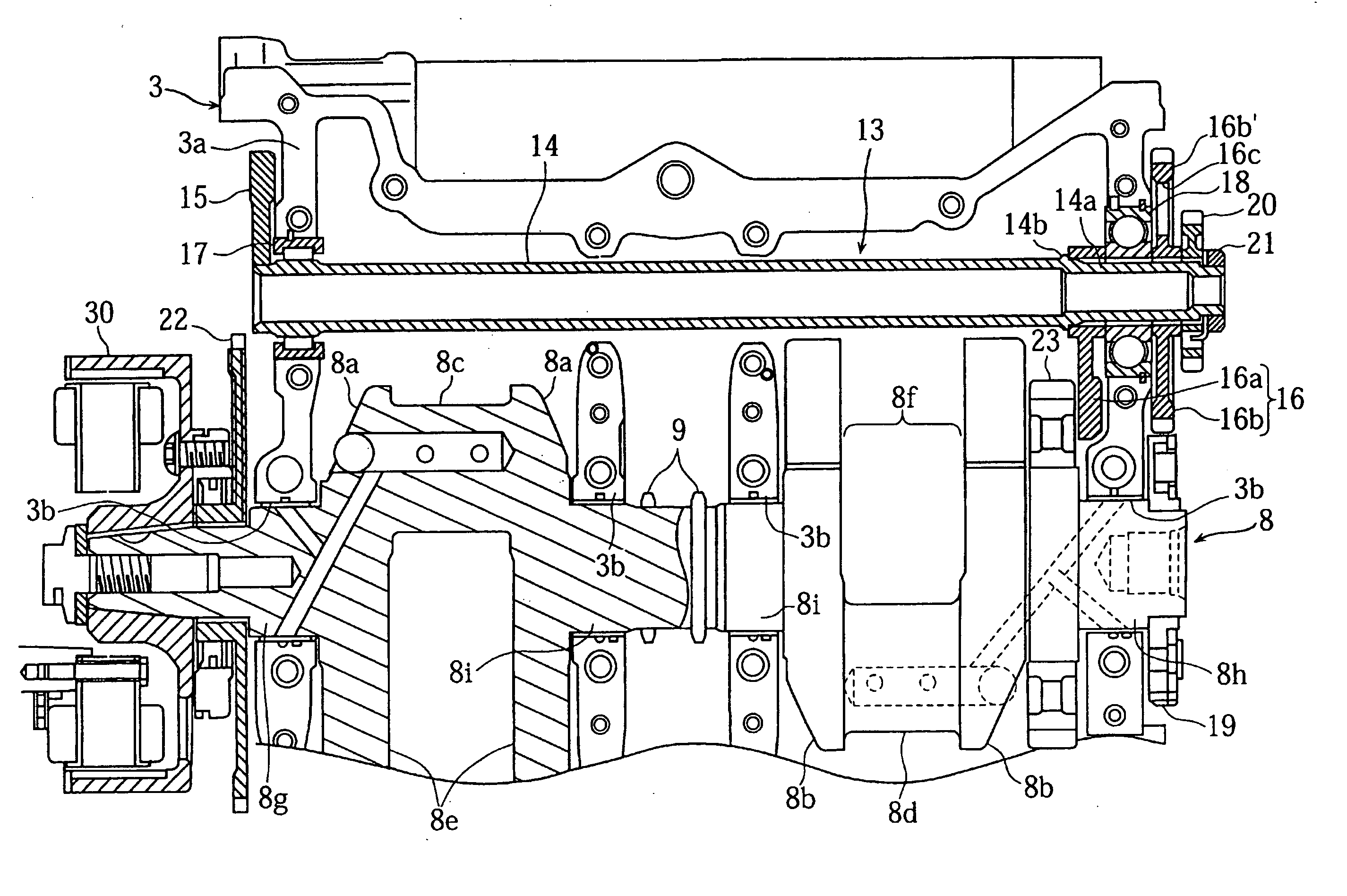
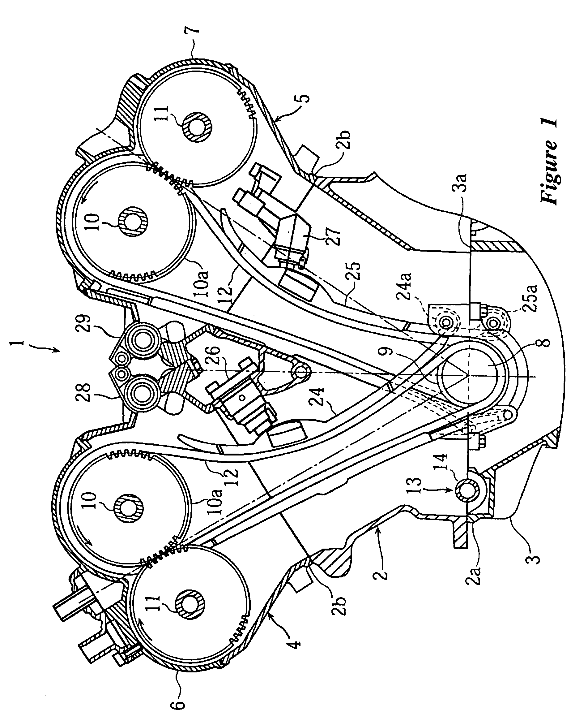
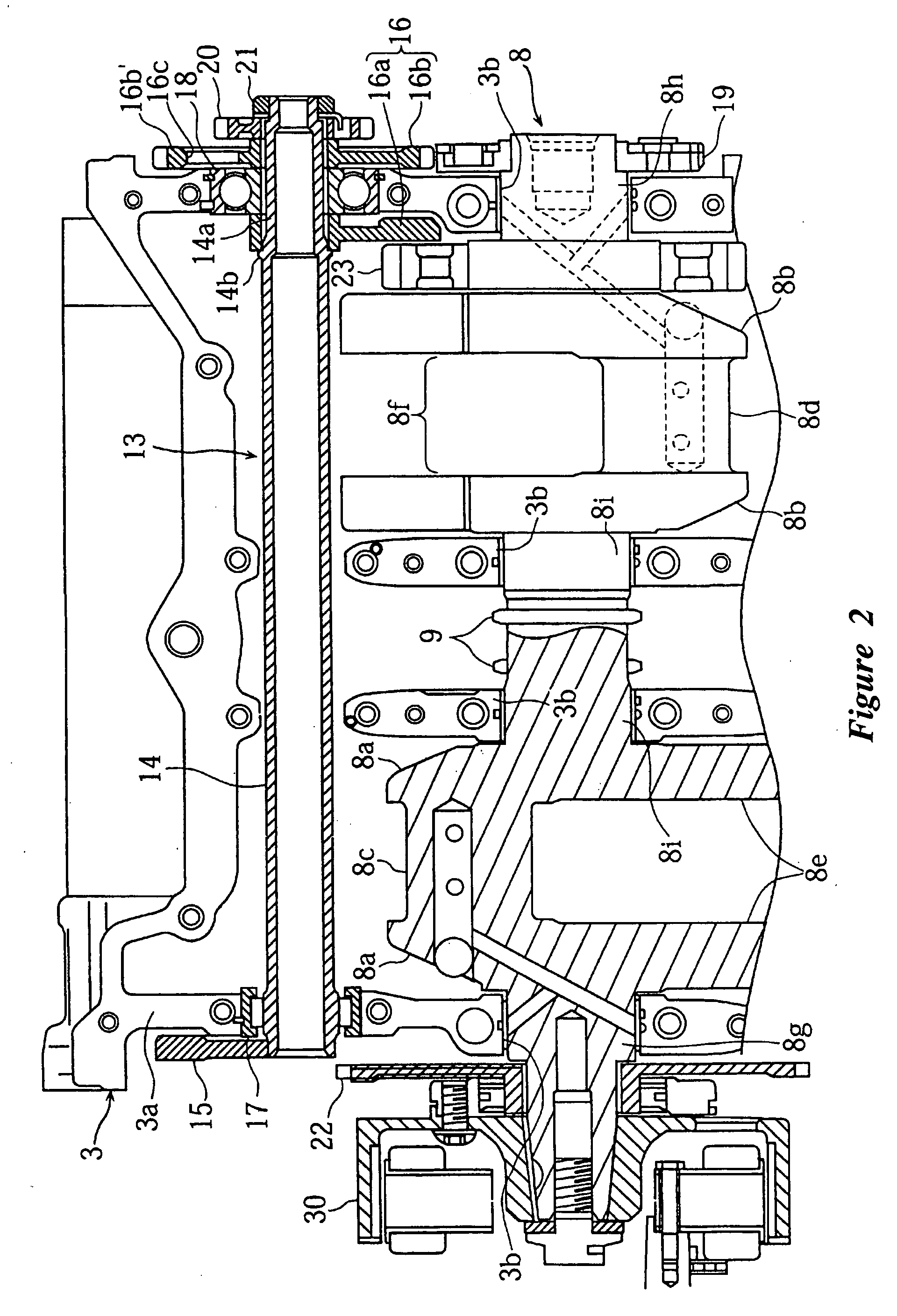
[0014] An embodiment of the present invention will be described below with reference to the accompanying drawings. FIGS. 1 through 3 illustrate an engine according to an embodiment of the present invention. In the drawings, reference numeral 1 denotes a water-cooled, four-stroke, V-type, four-cylinder engine, which has the following construction; however, the present balancer device can be used with other types and configurations of engines. The described engine thus is one type of engine on which the balancer device can be used. Additionally, while the engine I will be described with reference to the orientation shown in the drawings, it is understood that the engine can assume other orientations when used in practice, as will be understood by those skilled in the art.

[0015] A cylinder block 2 is formed with cylinder bores disposed to configure V-banks. A crankcase 3 is coupled to a lower mating face 2a of the cylinder block 2, and left and right cylinder heads 4, 5 are coupled to...


PUM


Abstract

An engine includes a balancer shaft that is supported at its both ends through bearings disposed within an engine crankcase. The balancer shaft lies generally parallel with a crankshaft and includes balancer weights, which are provided generally at the ends of the balancer shaft. At least one of the balancer weights is made up of first and second weight portions. The first and second weight portions are disposed on opposite sides of the corresponding bearing. In this manner, the bending moment on the shaft is reduced and, consequently, the balancer shaft can have a smaller diameter to reduce the size of the crankcase.

Description

CROSS-REFERENCE TO RELATED APPLICATIONS [0001] This application is based on and claims priority under 35 U.S.C. § 119 (a)-(d) to Japanese Patent Application No. 2004-237336, filed Aug. 17, 2005, the entire contents of which is hereby incorporated by reference. BACKGROUND OF THE INVENTION [0002] 1. Field of the Invention [0003] The present invention relates to an engine having a balancer shaft disposed in parallel with a crankshaft. [0004] 2. Description of the Related Art [0005] Prior engines have employed a balancer device, which includes a balancer shaft and balancer weights, to suppress vibration due to the reciprocating motion of pistons and connecting rods in an engine. Japanese Patent Publication No. JP-A-2003-56647 discloses an example of such a balancer device. In the disclosed balancer device, the balancer shaft is journalled at its both ends through bearings disposed within a crankcase and orientated in parallel with a crankshaft. The balancer weights mounted on the balanc...

Claims


Application Information

Patent Timeline
IPC IPC(8): F02B75/06
CPCF16F15/264Y10T74/2184Y10T464/50
Inventor NAKAYAMA, YOSHIHARU
Owner YAMAHA MOTOR CO LTD
Why Eureka
Try Eureka