Air-cooling battery pack having improved assembling structure

Active Publication Date: 2019-07-04
LG ENERGY SOLUTION LTD
2 Cites 2 Cited by

AI-Extracted Technical Summary

Problems solved by technology

For this reason, it is difficult to simplify the structure and the capacity of cells to be mounted is limited.
However, it is difficult to reduce the weight of the battery pack configured as above.
Moreover, a large space is required for installing components in the battery pack, and the space utilization in the thickness direction of the cells is reduced, thereby reducing the capacity and lowering the cooling performance due to low thermal conductivity.
In ad...

Benefits of technology

[0017]According to the present disclosure, the air-cooling battery pack gives the following effects.
[0018]First, since the BMS plate is completely assembled just by pushing the BMS plate into the battery pack, it is possible to reduce a process number and material costs in comparison to the conventional bolting assembling work.
[0019]Second, it is possible to stably support sliding of the BMS plate by using the air duct disposed in contact with the cell assembly.
[0...

Abstract

Disclosed is an air-cooling battery pack, which includes a cell assembly having a plurality of cells stacked therein; an air duct disposed to contact the cell assembly and having an air passage formed therein to allow a cooling air to move therethrough; a coupling groove formed at the air duct to elongate in a longitudinal direction; and a battery management system (BMS) plate having a BMS for managing the cells and assembled to the air duct by a slider slidably inserted into the coupling groove.

Application Domain

Cells structural combinationCell component details

Technology Topic

EngineeringBattery management systems +4

Image

  • Air-cooling battery pack having improved assembling structure
  • Air-cooling battery pack having improved assembling structure
  • Air-cooling battery pack having improved assembling structure

Examples

  • Experimental program(1)

Example

BEST MODE
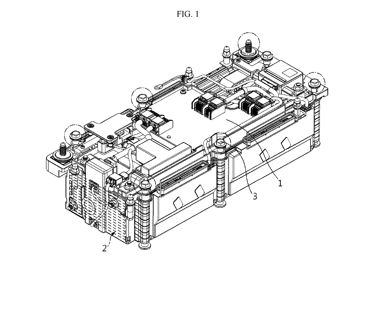
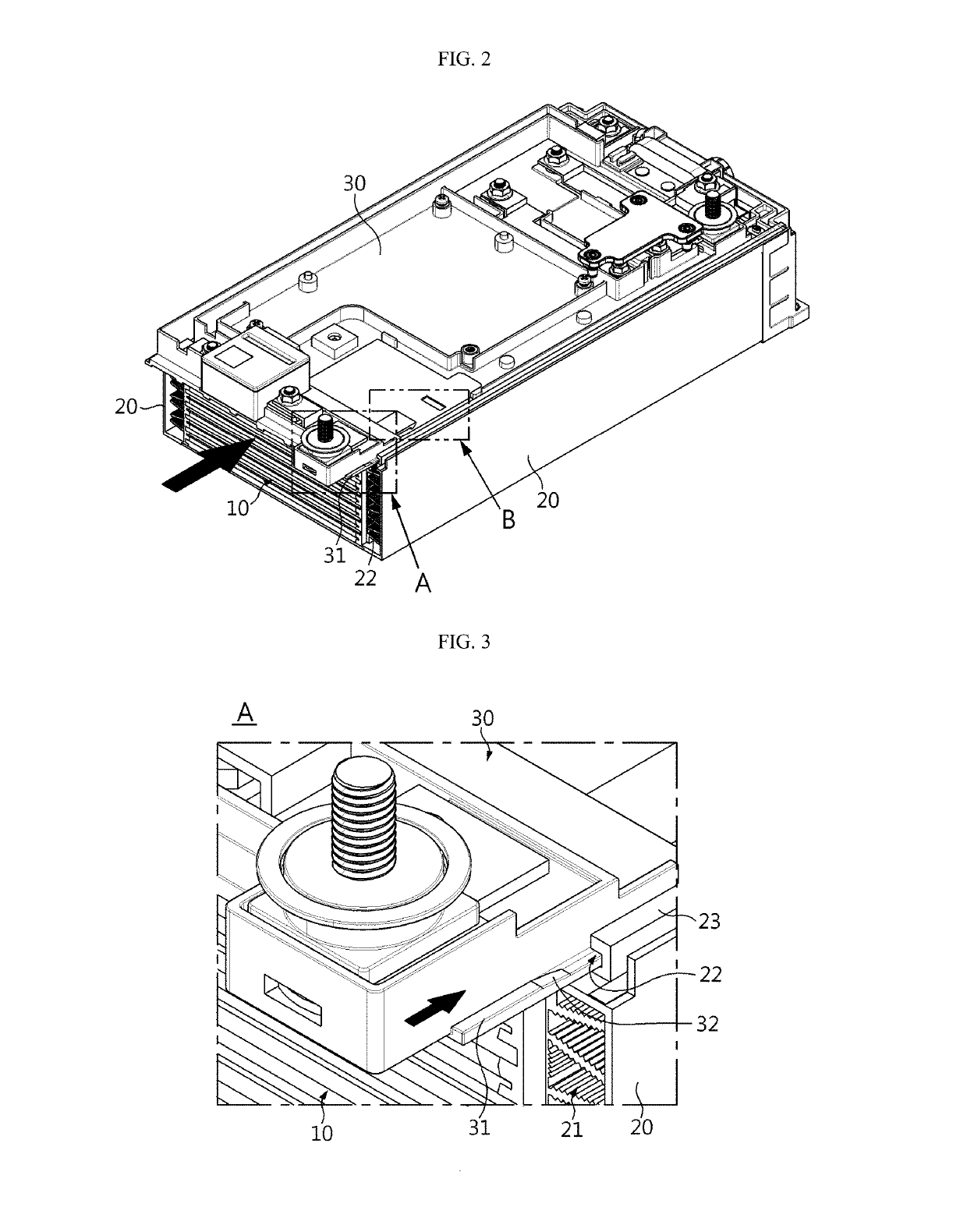
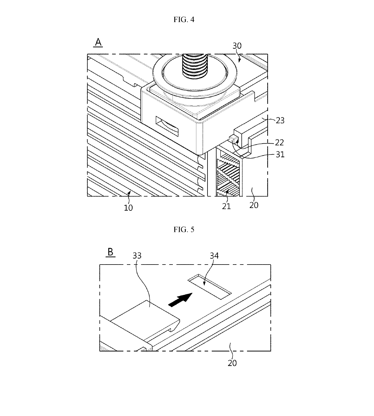
[0031]FIG. 2 is a perspective view showing an air-cooling battery pack according to an embodiment of the present disclosure.
[0032]Referring to FIG. 2, a battery pack according to an embodiment of the present disclosure includes a cell assembly 10 having a plurality of cells, air ducts 20 disposed to contact both side edges of the cell assembly 10, and a BMS plate 30 detachably assembled to coupling grooves 22 formed at the top of the air ducts 20.
[0033]Each cell of the cell assembly 10 has a thin plate-like body and preferably has a pouch cell structure. The pouch cell includes a positive electrode, a separator and a negative electrode, which are alternately stacked so that an electrode tab is drawn out from at least one side thereof. The positive electrode and the negative electrode are fabricated by coating slurry containing an electrode active material, a binder resin, a conductive agent and other additives to at least one side of a current collector. In the case of a positive electrode, a common positive electrode active material such as a lithium-containing transition metal oxide may be used as the electrode active material. In the case of a negative electrode, a common negative electrode active material such as a lithium metal capable of intercalating and de-intercalating lithium ions, a carbonaceous material, a metal compound, or compounds thereof may be used as the electrode active material. In addition, the separator may adopt a common porous polymer film used in a lithium secondary battery.
[0034]A common electrolyte for a lithium secondary battery may be employed as the electrolyte contained in a pouch case together with the electrode assembly. The pouch case is formed of sheet material and has an accommodating portion for accommodating the electrode assembly. Preferably, the pouch case is formed by coupling a first case and a second case, which are prepared by processing a sheet material into a predetermined shape. The sheet material of the pouch case has a multi-layered structure including an outer resin layer provided at an outermost side and made of an insulating material such as polyethylene terephthalate (PET) or nylon, a metal layer made of an aluminum material to maintain mechanical strength and prevent penetration of moisture and oxygen, and an inner resin layer made of a polyolefin-based material and serving as a sealing material due to thermal adhesiveness.
[0035]In the sheet material of the pouch case, a predetermined adhesive resin layer may be interposed between the inner resin layer and the metal layer and between the outer resin layer and the metal layer, if necessary. The adhesive resin layer is intended for smooth attachment between different kinds of materials and is formed as a single layer or a multilayer. The adhesive material may be commonly made of a polyolefin resin, or a polyurethane resin for smooth processing, or a mixture thereof.
[0036]In the cell assembly 10, the plurality of cells are disposed at predetermined intervals in the thickness direction to form a substantially stacked structure.
[0037]The air duct 20 is for air-cooling the cell assembly 10 and includes a duct made of an aluminum material and having an air passage for moving a cooling air. An outer surface of the air duct 20 oriented toward the cell assembly 10 is disposed in contact with the edge portion of the cell assembly 10. At this time, it is preferable that a heat transfer material made of a thermal interface material (TIM) having high thermal conductivity is interposed between the edge portion of the cell assembly 10 and the air duct 20.
[0038]A truss structure 21 formed by repeatedly arranging frames to form a substantially triangular shape is provided inside the duct of the air duct 20 to improve the cooling performance and provide sufficient mechanical rigidity for protecting the cell assembly 10 from an external impact or the like.
[0039]In addition, a plurality of uneven patterns are formed on the surface of the truss structure 21 of the air duct 20. The uneven patterns improve the cooling performance by increasing the internal surface area of the air duct 20.
[0040]The air duct 20 is provided on both sides of the cell assembly 10, respectively, and is disposed so that the longitudinal direction thereof is extended identical to the longitudinal direction of the cell assembly 10.
[0041]A coupling groove 22 to which the BMS plate 30 may be assembled is provided at the top of the air duct 20. Preferably, the coupling groove 22 may be provided by a guide rib 23 formed at the top of the air duct 20. The guide rib 23 is formed integrally with the air duct 20 to extend in the longitudinal direction at the top surface of the air duct 20, and the coupling groove 22 is formed at the guide rib 23 such that the coupling groove 22 has a section of a ‘⊂’ shape and its opening is oriented toward the inside of the battery pack.
[0042]The BMS plate 30 is a circuit board assembly to which a battery management system (BMS) for managing the cells and various electrical components required for the battery pack are mounted. The BMS plate 30 may be provided as a single plate or a plurality of plates assembled.
[0043]The BMS plate 30 is disposed at an upper portion of the stacked structure of the cell assembly and both side edges of the BMS plate 30 are assembled by being slidably inserted into the coupling groove 22 of the air duct 20. For this, as shown in FIG. 3, a bar-type slider 31 shaped and sized to be inserted into the coupling groove 22 is formed at both side edges of the BMS plate 30 to extend in the longitudinal direction of the BMS plate 30.
[0044]The slider 31 is preferably integrally formed at the BMS plate 30 by plastic injection molding. A gradient structure 32 inclined to have a gradually increasing thickness in a direction opposite to the inserting direction is formed in a portion of the slider 31. The gradient structure 32 is for pressing the slider 31 into the coupling groove 22 and prevents the BMS plate 30 from being separated from the air duct 20 due to external vibration or impact or being damaged by shaking.
[0045]Since the guide rib 23 forming the coupling groove 22 is made of aluminum material integrally with the air duct 20, it is preferable that the slider 31 is made of plastic material and tightly inserted into the coupling groove 22. It is preferable that the gradient structure 32 is located close to a rear portion of the slider 31 so that the slider 31 is tightly fitted into the coupling groove 22 and simultaneously the BMS plate 30 is completely inserted.
[0046]In order to fix the position of the BMS plate 30 assembled in a sliding manner more firmly, a stopper 33 having a hook structure and made of plastic material is provided on a part of the BMS plate 30. The stopper 33 may be integrally formed when the BMS plate 30 is formed. In addition, a fixing plate 34 having a hole or groove form corresponding to the stopper 33 is provided at the air duct 20 or a predetermined support plate located under the BMS plate 30. When the slider 31 is completely inserted, the stopper 33 is hooked to the fixing portion 34 to effectively prevent movement of the BMS plate 30.
[0047]The battery pack configured as above according to an embodiment of the present disclosure is assembled by disposing the air ducts 20 at both side edges of the cell assembly 10 and then slidably coupling the BMS plate 30 to the air duct 20 at a location above the cell assembly 10.
[0048]The truss structure 21 is provided inside the air duct 20 to secure sufficient rigidity and increase the heat transfer area. In addition, due to the plurality of uneven patterns formed at the truss structure 21, the heat transfer area is further increased to improve the cooling performance.
[0049]The cooling air introduced into one opening of the air duct 20 moves along the air passage inside the air duct 20 and is forcibly discharged out at the opposite opening, during which, the cell assembly 1 is air-cooled.
[0050]In the assembling process of the BMS plate 30, a front end of the slider 31 provided at the edge of the BMS plate 30 is pushed and inserted into the coupling groove 22 of the guide rib 23 integrated at the top of the air duct 20 so that the plate30 is disposed at the upper portion of the cell assembly 10.
[0051]Immediately before the BMS plate 30 is completely inserted into the air duct 20, the BMS plate 30 is gradually inserted more tightly due to the gradient structure 32 of the slider 31, and finally the stopper 33 is hooked to the fixing portion 34 to fix the assembled state.
[0052]By means of the structure in which both side edges of the BMS plate 30 are coupled in contact with the air duct 20, the heat generated from the BMS plate 30 may be efficiently conducted to the air duct 20 and cooled.
[0053]The battery pack according to the present disclosure may simplify the assembling process and reduce the material cost since the bolting process may be omitted when the BMS plate 30 is coupled, compared to the conventional battery pack.
[0054]In addition, since the battery pack is cooled by the air ducts 20 disposed at both sides of the cell assembly, the space utilization in the cell thickness direction may be enhanced. Also, by means of the truss structure 21 provided inside the air duct 20, it is possible to sufficiently secure the mechanical stiffness and improve the cooling performance.
[0055]The present disclosure has been described in detail. However, it should be understood that the detailed description and specific examples, while indicating preferred embodiments of the disclosure, are given by way of illustration only, since various changes and modifications within the scope of the disclosure will become apparent to those skilled in the art from this detailed description.
INDUSTRIAL APPLICABILITY
[0056]If the present disclosure is applied, the assembling work for inserting the BMS plate into the battery pack is improved, thereby reducing a process number and material costs, compared to the conventional bolting assembling work.

PUM

no PUM

Description & Claims & Application Information

We can also present the details of the Description, Claims and Application information to help users get a comprehensive understanding of the technical details of the patent, such as background art, summary of invention, brief description of drawings, description of embodiments, and other original content. On the other hand, users can also determine the specific scope of protection of the technology through the list of claims; as well as understand the changes in the life cycle of the technology with the presentation of the patent timeline. Login to view more.

Similar technology patents

Heavy duty tire

ActiveUS20210213782A1improve cool performanceexcellent effect
Owner:BRIDGESTONE CORP

Thermal management system for electric vehicles

PendingUS20220266651A1increase flow rateimprove cool performance
Owner:HYUNDAI MOTOR CO LTD +1

Nuclear Reactor Containment Vessel and Nuclear Reactor

InactiveUS20160372217A1improve cool performance
Owner:HITACHI LTD

Cooling system for vehicle

InactiveUS20140166242A1improve cool performanceimprove performance
Owner:HYUNDAI MOTOR CO LTD +2

Cylinder head

ActiveUS20220074365A1increase amount of coolantimprove cool performance
Owner:HYUNDAI MOTOR CO LTD +1
Why Eureka
Try Eureka