Check patentability & draft patents in minutes with Patsnap Eureka AI!

Magnetic filter with drain and removable external magnetic element

a magnetic element and filter technology, applied in the field of magnetic filters, can solve the problems of less effective removal of magnetic particles by filter types, more likely damage to seals, etc., and achieve the effect of improving the collection efficiency of magnets and reducing static pressur

Active Publication Date: 2019-10-10
ADEY HLDG
View PDF0 Cites 0 Cited by
  • Summary
  • Abstract
  • Description
  • Claims
  • Application Information

AI Technical Summary

Benefits of technology

This patent describes a connection assembly for a filter that includes an inlet, outlet, and drain outlet. The filter includes a thin-walled stainless steel canister with an open end, which eliminates the need for valves and connectors and allows for easy manufacturing. The canister is placed over a magnetic element that matches the shape of the canister, creating an aesthetically pleasing appearance. The magnetic element is pushed away from the outer walls of the canister to ensure optimal field performance. The invention also includes a spring member to push the magnets towards the canister. The invention improves filter performance without sacrificing static pressure drop.

Problems solved by technology

Also, repeatedly opening the canister makes damage to the seal more likely.
Unfortunately, this type of filter is generally less effective at removing magnetic particles, because the strength of the magnet is attenuated by the thickness of the wall of the canister.

Method used


Image

  • Magnetic filter with drain and removable external magnetic element
  • Magnetic filter with drain and removable external magnetic element
  • Magnetic filter with drain and removable external magnetic element

Examples


Embodiment Construction

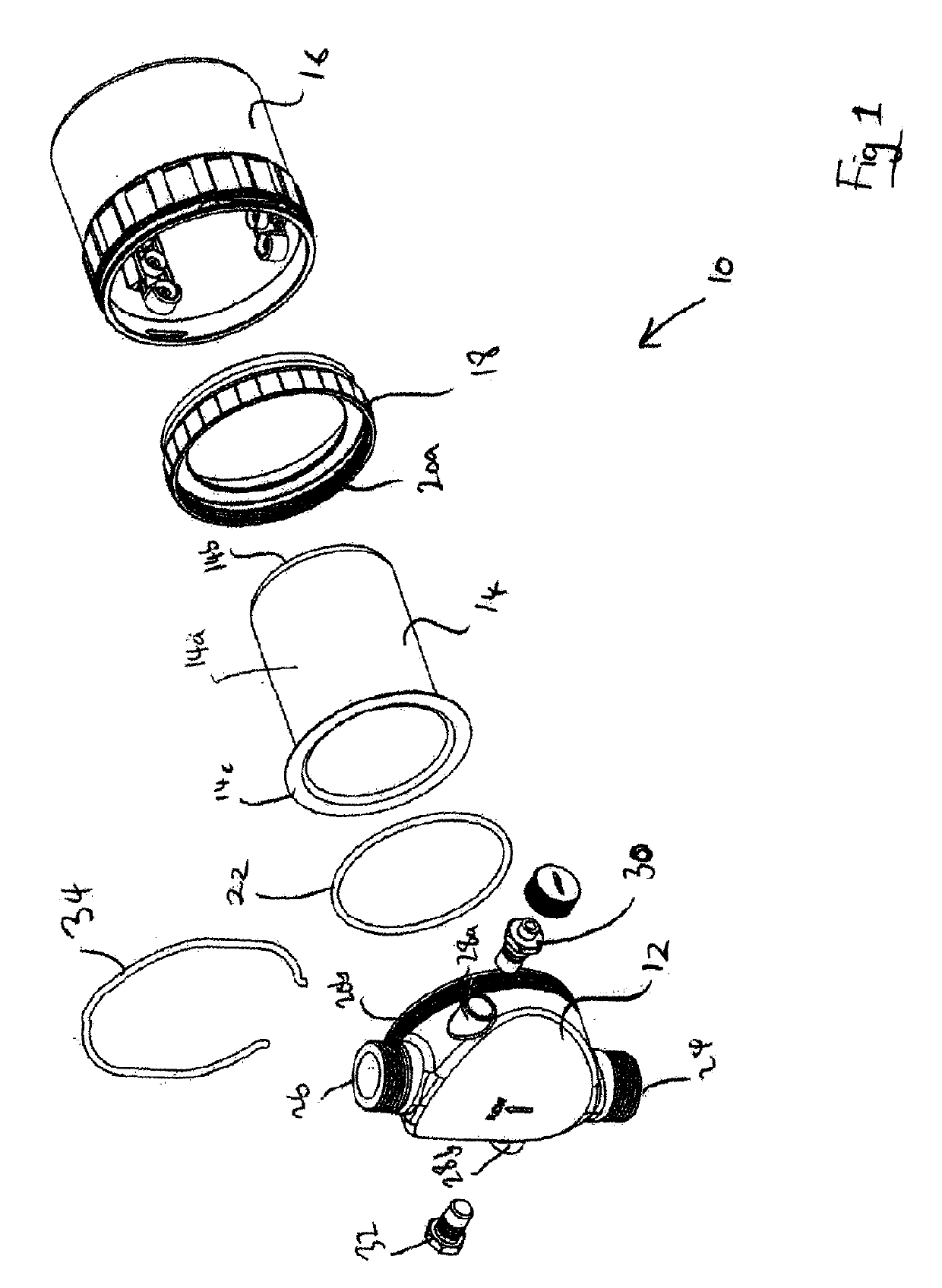
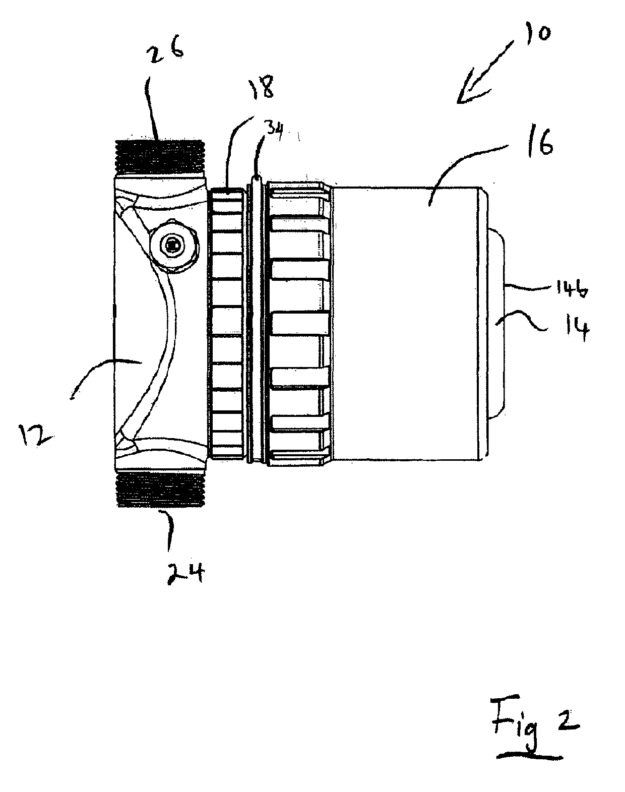
[0046]Referring firstly to FIGS. 1 and 2, a magnetic filter for a central heating system is indicated generally at 10. The magnetic filter comprises a connection assembly 12, a canister 14, and a magnetic element 16. The overall shape of the assembled filter is substantially cylindrical, as seen best in FIG. 2.

[0047]The connection assembly 12 is located at one end of the cylindrical filter, and forms a substantially circular end cap on the canister 14. The connection assembly includes an inlet port 24 and an outlet port 26. The canister 14 is cylindrical and open at one end. In other words, the canister 14 has a curved wall 14a and a flat end wall 14b. A rim 14c surrounds the open end, extending outwardly from an edge of the curved wall, forming a circumferential flange.

[0048]The canister 14 is assembled onto the connection assembly 12 by placing the rim 14c against the connection assembly 12, and then providing a retaining ring 18 behind the rim 14c of the canister 14. The retainin...


PUM

PropertyMeasurementUnit
magneticaaaaaaaaaa
polarityaaaaaaaaaa
non-magneticaaaaaaaaaa

Abstract

A magnetic filter 10 for a central heating system is disclosed, the filter 10 including a connection assembly 12, a canister 14, and a magnetic element 16, the connection assembly 12 including an inlet 24 and an outlet 26 for connection to a central heating circuit; the canister 14 having an interior separation chamber which is fluidly connected with the inlet 24 and outlet 26 for allowing fluid to flow into the inlet 24, through the separation chamber, and out of the outlet 26; and the magnetic element 16 being removably positionable on the outside of the canister 14, the canister 14 and the connection assembly 12 forming a sealed flow path comprising the inlet 24, the interior separation chamber and the outlet 26, and the connection assembly 12 further including a closable drain outlet 28b for draining fluid and magnetic particles from within the canister 14, internally of the magnetic element 16.

Description

CROSS-REFERENCE TO RELATED APPLICATION[0001]This application claims the benefit of priority of and is a continuation of U.S. application Ser. No. 15 / 565,325 which is a national stage application claiming the benefit of priority of PCT / GB2016 / 050963, each of which are incorporated herein by reference in their entireties.FIELD OF THE INVENTION[0002]The present invention relates to a magnetic filter for a central heating system, and in particular to a filter having a magnet on the outside of a sealed separation chamber.BACKGROUND TO THE INVENTION[0003]Magnetic filters, which are designed to remove magnetic particles entrained in system water, are now commonly installed in central heating systems. Central heating systems include a main circuit which carries system water around the system. The system water often contains various chemicals, for example inhibitors, as well as magnetic and non-magnetic dirt which is picked up from radiators and other devices in the circuit.[0004]All magneti...

Claims


Application Information

Patent Timeline
Patent Type & Authority Applications(United States)
IPC IPC(8): B03C1/28F28F19/01B01D21/00B01D35/06F24D19/00B03C1/30C02F1/48
CPCB01D35/06B01D21/0009F24D19/0092F28F19/01B03C2201/28B03C1/288B03C2201/18B03C1/30C02F1/482B03C1/0332C02F2201/006C02F2307/14B03C1/28F24D3/00
Inventor ADEY, CHRISTOPHERDOWNIE, SIMONALBROW, ROBERT CHARLES
Owner ADEY HLDG
Features
  • R&D
  • Intellectual Property
  • Life Sciences
  • Materials
  • Tech Scout
  • Unparalleled Data Quality
  • Higher Quality Content
  • 60% Fewer Hallucinations
Learn More