Brackets for Temporary Support of a Rail Between Upright Posts During Construction of a Fence or the Like

Inactive Publication Date: 2019-10-17
THE EZ FENCE BRACKET CO
View PDF0 Cites 0 Cited by
  • Summary
  • Abstract
  • Description
  • Claims
  • Application Information

AI Technical Summary

Benefits of technology

The invention is a device for temporarily supporting an end of a rail during installation between a pair of upright posts. The device includes a bracket that is placed on the lateral side of the post and a seat for receiving the rail. The bracket has an inner face that faces the post, an outer face, and a bracing flange that reaches perpendicularly inward from the inner face at a lower elevation than the top end of the bracket. The bracket is designed to squaren the rail with the post. The device also includes a tape measure slot for measuring the distance between the two posts. The bracket can be easily fastened to the post using a fastening hole. The device helps to accurately position the rail during installation.

Problems solved by technology

These brackets are typically formed from a bent metal plate with a galvanized coating, and thus detract from the aesthetic of a purely wooden fence construction in which wooden rails are directly fastened to wooden posts.
The permanent brackets also represent an added material cost relative to a purely wooden construction.
The device is incapable of placing the rail in an inline position contained entirety between the two posts with the ends of the rail abutted against lateral sides of the posts that face toward one another.
The device also lacks means for automatic alignment in a properly squared orientation on the post.
The flexible strap is only capable of providing support, and does not provide any guidance for proper alignment of the rail on the post.
U.S. Pat. No. 9,344,674 discloses another temporary fence rail support that once again is specifically designed to support a rail board in offset relation to the post at the outer side thereof, and lacks any means for self-alignment of the support on the post to ensure proper alignment of the rail.
Once again, the design is intended for offset rail placement, and is not operable to support a rail in an inline position between lateral sides of the posts.
Designed for use with structural steel, the beam seat employs bulky, complex design that occupies all four sides of the column, features two clamps for tightening on the column in one direction, and a wedge for mechanism for tightening on the column in the other direction.
The lower part of the support that carries the bottom of the fence panel is automatically placed at a suitable elevation downward from the top of the post, but the support lacks any means for properly squaring the panel relative to the post.

Method used


Image

  • Brackets for Temporary Support of a Rail Between Upright Posts During Construction of a Fence or the Like
  • Brackets for Temporary Support of a Rail Between Upright Posts During Construction of a Fence or the Like
  • Brackets for Temporary Support of a Rail Between Upright Posts During Construction of a Fence or the Like

Examples


first embodiment

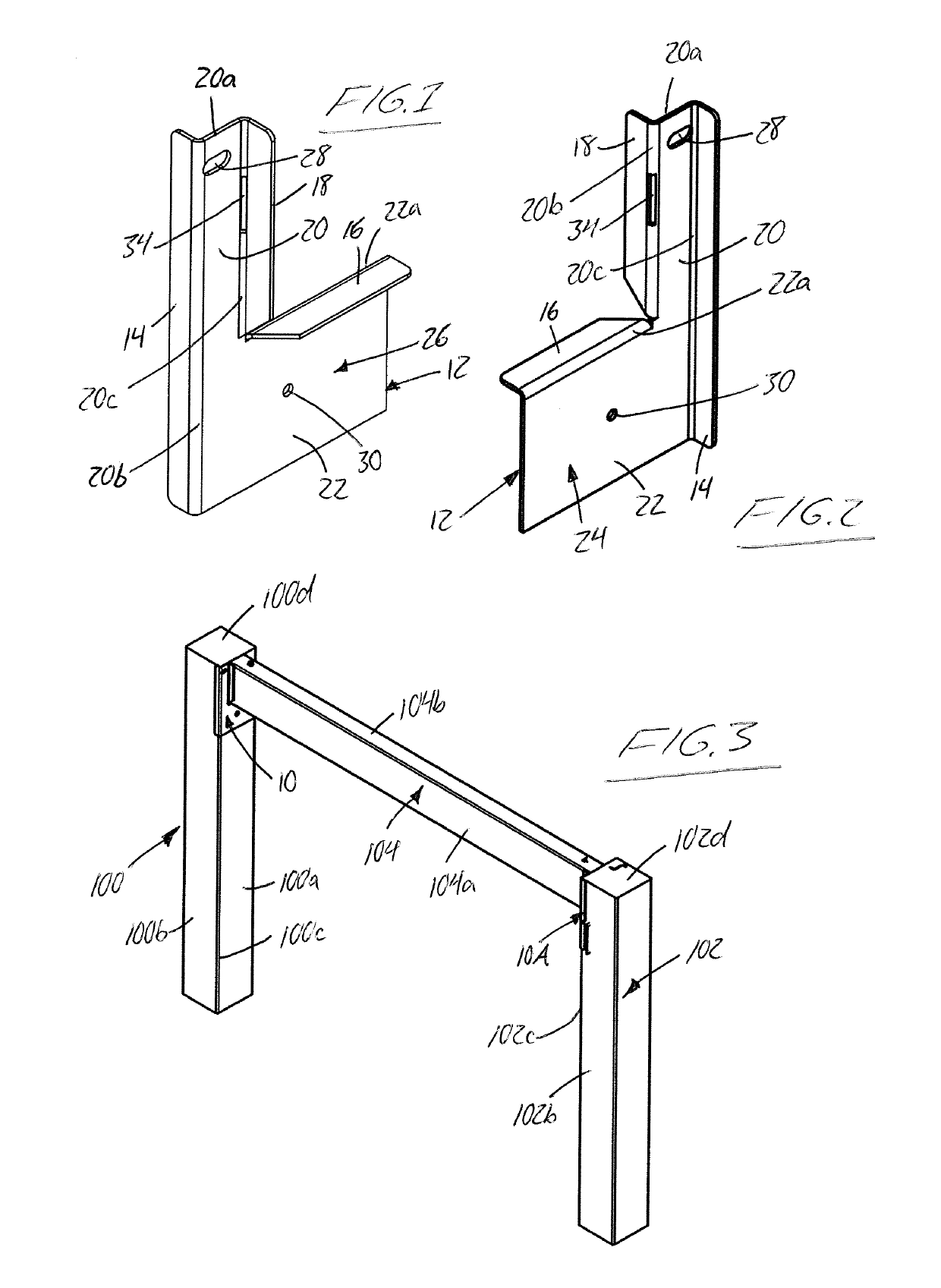
[0068]FIG. 1 illustrates one bracket 10 of a two-bracket rail support system according to the present invention. The bracket 10 is shown from opposing sides in FIGS. 1 and 2, and is referred to herein as the left bracket intended for use together with a cooperating right bracket of mirrored configuration to the left bracket. Each bracket is intended to temporarily support a respective end of a fence rail on a respective one of two neighbouring fence posts during construction of a fence, as shown in FIG. 3. Each fence post 100, 102 stands vertically upright from an area of ground beneath which the bottom end of the fence post is buried to anchor it in this upright position. Each fence post has a square cross-sectional shape in horizontal cross-sectional planes that lie perpendicularly to the central vertical axis of the fence post. Once installed, the rail 104 spans horizontally between the two vertical posts 100, 102 in elevated relation above the ground in an in-line position betwe...

third embodiment

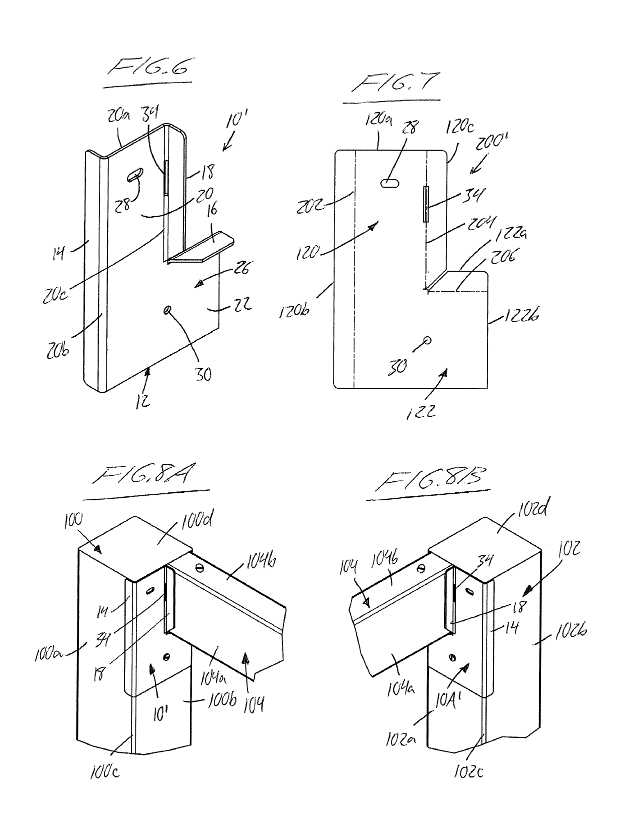
[0088]To allow optional use of differently sized rails, and more particularly rails of different edge-to-edge face width (which corresponds to the height of the rail in its installed face-out edge-up orientation), the shoulder of each third embodiment bracket 10″, 10A″ features two shoulder flanges 18A, 18B instead of a single shoulder flange spanning the full height from the seating flange 16 to the top end 20a of the bracket. A notch or slot 210 is cut into the inner edge vertical leg 120 of the blank 200″, as shown in FIG. 10, at a height above the upper bend line 206 that equals the full edge-to-edge face width of the smaller of the two compatible rail sizes. In the finished bracket 10″, 10A″, this creates a gap 19 between the two shoulder flanges 18A, 18B at a height above the seating flange 16 that equals the edge-to-edge face width of the smaller of the two compatible rails sizes. So, in the illustrated embodiment intended for use with either 2×4 or 2×6 rails, the gap 19 is s...


PUM


Abstract

For temporarily supporting a rail during installation between a pair of upright posts, a bracket features an inner face for placement against a lateral side of the first post, and an outer face lying opposite the inner face. An upright bracing flange projects inwardly from the inner face of the bracket at an upright edge thereof to embrace a corner of the first post in squared relation thereto. A seat extends perpendicularly away from the bracing flange to receive an underside of the rail and place an end of the rail closely adjacent the lateral side of the first post. An upright shoulder is situated above the seat in perpendicular relation thereto and parallel relation to the bracing flange to receiving a face of the rail. Seating and abutting the rail with the seat and the upright shoulder of the bracket thus squares the rail with the post.

Description

CROSS-REFERENCE TO RELATED APPLICATIONS[0001]This application claims benefit under 35 U.S.C. 119(e) of U.S. Provisional Application No. 62 / 642,815, filed Mar. 14, 2018, the entirety of which is incorporated herein by reference.FIELD OF THE INVENTION[0002]The present invention relates generally to devices for use in construction of a fence or other structure in which horizontal rails are suspended between upright posts, and more particularly to devices for temporarily supporting the two ends of the rail to allow properly aligned installation by a single person.BACKGROUND[0003]Brackets and other devices for supporting of a fence rail between two fence posts during construction of a fence have previously been proposed to reduce labour requirements by allowing a single installer properly align and fasten the rail in place, thus avoiding the need for two installation personnel to align, hold and fasten the rail.[0004]Among the solutions proposed in the prior art are permanent hardware br...

Claims


Application Information

Patent Timeline
IPC IPC(8): E04H17/14E04H17/26
CPCE04H17/1421E04H17/26F16B7/0486E04H17/1452E04H17/1488E04H17/1417
Inventor WALL, BRUCETAYLOR, ANGUS
Owner THE EZ FENCE BRACKET CO
Why Eureka
Try Eureka