Hydroelectric power generation device using multistage cascade structure

a power generation device and cascade technology, applied in mechanical energy handling, mechanical equipment, machines/engines, etc., can solve the problems of difficult to rotate the driving shaft, the uppermost waterwheel is not smooth, and the waterfall distance to each waterwheel is difficult to increase, so as to achieve the effect of saving the electricity needed for pump operation, generating sufficient rotation power, and stably producing electricity

Inactive Publication Date: 2020-02-27
PARK JUNGCHI
View PDF4 Cites 5 Cited by
  • Summary
  • Abstract
  • Description
  • Claims
  • Application Information

AI Technical Summary

Benefits of technology

[0014]According to the present invention, since the plurality of waterwheels are independently operated while respectively interacting with the generators, electricity can be stably produced while the plurality of waterwheels are independently rotated. In addition, electricity necessary for operating the pump can be saved because the pump is controlled in such a manner that after water is supplied from the lower water tank to the upper water tank to a predetermined water level, the pump is intermittently operated to supply water to the upper water tank according to results of detection of the water level sensors.
[0015]In addition, according to the present invention, the axles of the generators are rotated at a relatively high speed according to the diameter difference between the pulleys installed on the ax...

Problems solved by technology

However, in the disclosed hydroelectric power generation device, it is difficult to increase the distance water falls to each waterwheel because a plurality of small waterwheels are used, and thus the waterwheels are rotated by low power.
Moreover, since the waterwheels arranged in multiple stages are connected to a single driving shaft through gears to rotate the driving shaft, it is difficult to rotate the driving shaft only b...

Method used


Image

  • Hydroelectric power generation device using multistage cascade structure
  • Hydroelectric power generation device using multistage cascade structure
  • Hydroelectric power generation device using multistage cascade structure

Examples


Embodiment Construction

Technical Problem

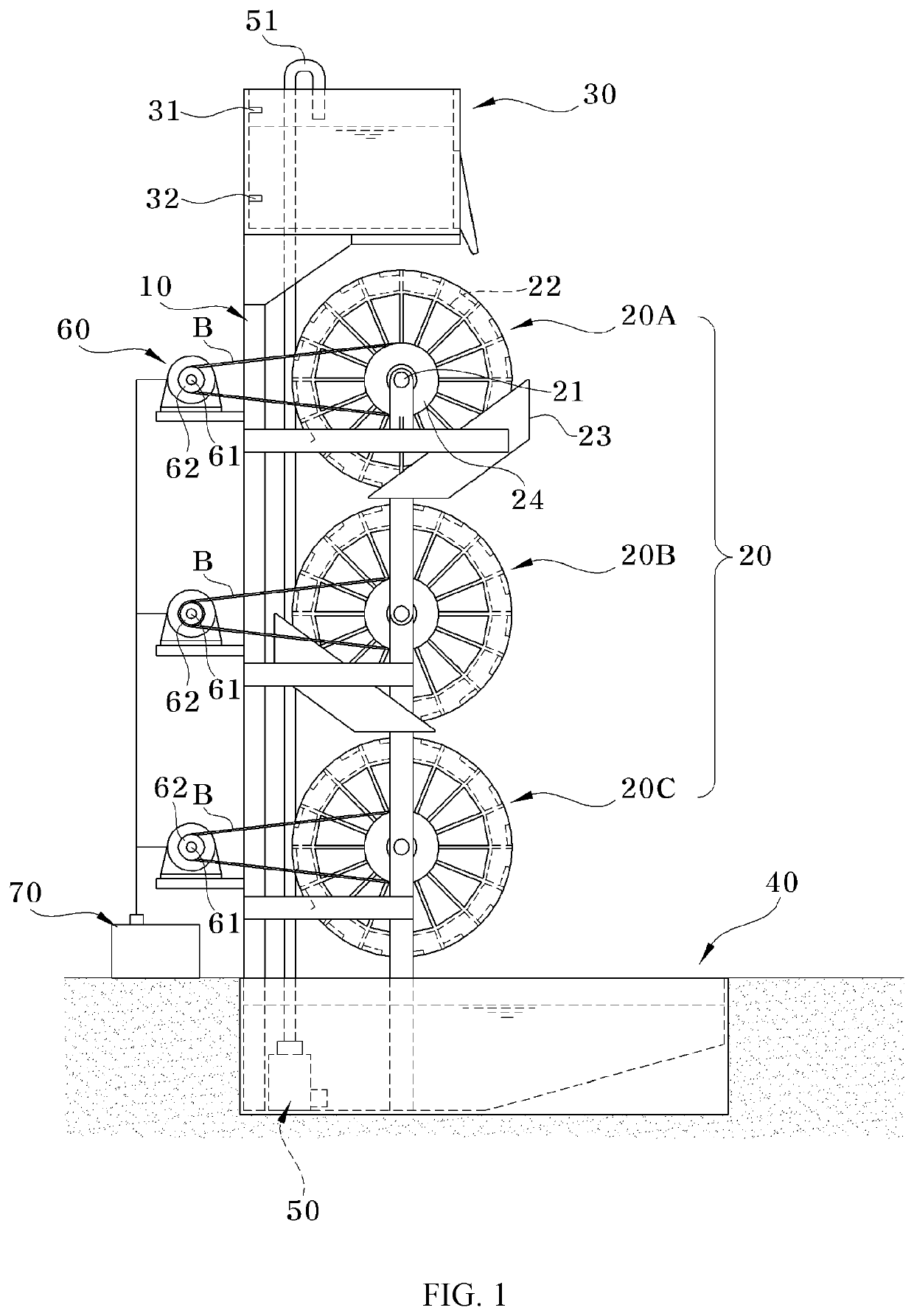
[0009]Accordingly, the present invention is proposed to solve the above-described problems of electric power generation devices having a multistage waterwheel structure of the related art, and an object of the present invention is to provide a hydroelectric power generation device having a multistage cascade structure in which waterwheels can be easily rotated without using a motor when the waterwheels are initially rotated and electricity can be continuously produced without continuously operating a pump.

Solution to Problem

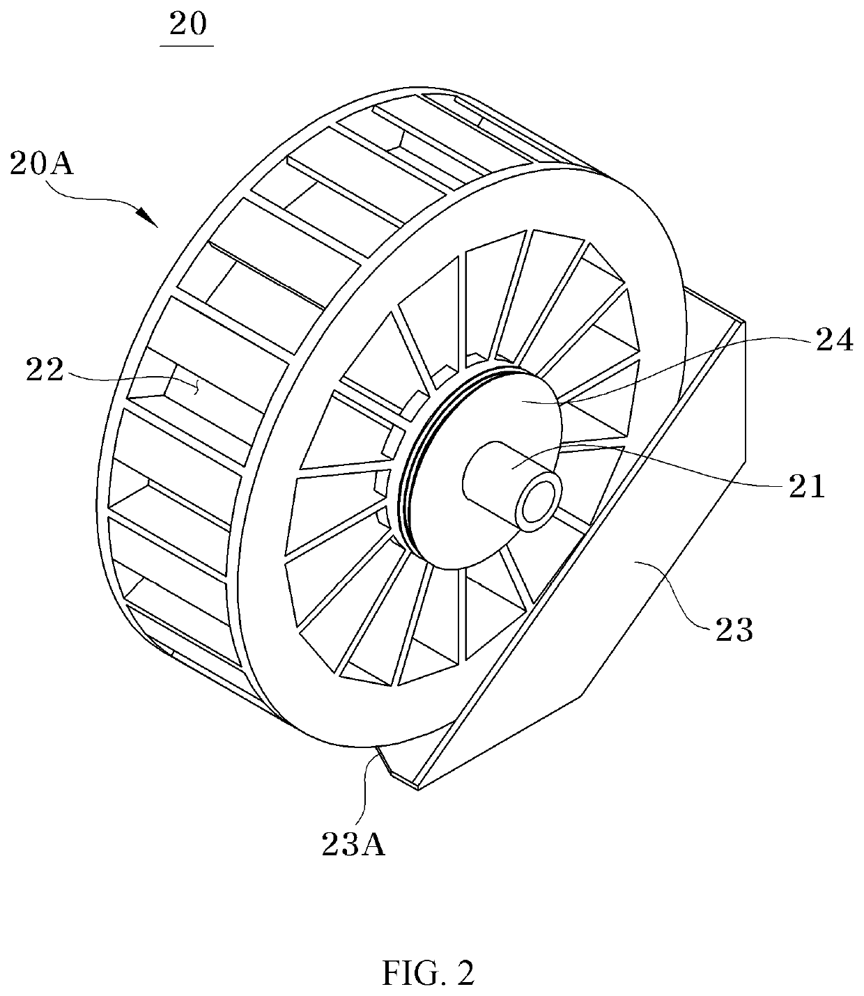
[0010]The object of the present invention is achieved by a hydroelectric power generation device using a multistage cascade structure, the hydroelectric power generation device including: a support having a predetermined length and installed in a vertical direction; a plurality of waterwheels each including a horizontal axle rotatably installed on the support and a plurality of buckets radially arranged around the axle; an upper water tank and a ...


PUM


Abstract

The present invention relates to a hydroelectric power generation device using a multistage cascade structure. The hydroelectric power generation device includes: a support (10) having a predetermined length and installed in a vertical direction; a plurality of waterwheels (20) each including a horizontal axle (21) rotatably installed on the support (10) and a plurality of buckets (22) radially arranged around the axle (21); upper and lower water tanks (30, 40) respectively installed on upper and lower portions of the support (10) and respectively containing predetermined amounts of water; a pump (50) installed in the lower water tank (40) to supply water from the lower water tank (40) to the upper water tank (30); generators (60) respectively installed on the axles (21) of the waterwheels (20); and a charging battery (70) configured to store electricity produced by the generators (60). Thus, according to the present invention, electricity can be stably and effectively produced.

Description

TECHNICAL FIELD[0001]The present invention relates to a hydroelectric power generation device using a multistage cascade structure, and more particularly, to a hydroelectric power generation device using a multistage cascade structure in which a plurality of waterwheels are vertically installed to operate generators and thus produce electricity while the waterwheels are rotated by water falling by gravity along the waterwheels.BACKGROUND ART[0002]In general, various methods for producing electricity using thermal power, water power, wind power, solar power, and the like have been known, and devices for producing electricity by using water power (hereinafter referred to as hydroelectric power generation devices) have been widely used because they produce low environmental pollution and have a simple structure.[0003]In general, such hydroelectric power generation devices have a structure in which rotation power generated as a waterwheel is rotated by water falling by gravity is used t...

Claims


Application Information

Patent Timeline
IPC IPC(8): F03B7/00H02K7/18H02K11/00F03B13/06
CPCF03B13/06H02K7/1823F03B7/00H02K11/0094F03B7/003F03B17/005F05B2240/40F05B2260/4021Y02E10/20Y02E60/16F03B11/008F03B15/00F05B2220/32F05B2220/706
Inventor PARK, JUNGCHI
Owner PARK JUNGCHI
Why Eureka
Try Eureka