Intake device for internal combustion engine

a technology for internal combustion engines and intake devices, which is applied in the direction of combustion engines, combustion-air/fuel-air treatment, charge feed systems, etc., can solve the problems of difficult to generate a strong tumble flow in the combustion chamber of internal combustion engines, and difficult to generate an intended tumble flow, etc., to achieve the effect of improving the combustion efficiency

Inactive Publication Date: 2008-11-20
DENSO CORP
View PDF4 Cites 5 Cited by
  • Summary
  • Abstract
  • Description
  • Claims
  • Application Information

AI Technical Summary

Benefits of technology

[0011]It is an object of the present invention to provide an intake device of an internal combustion engine capable of making an opening area of a second throttle portion larger than an opening area of a first throttle portion when rotation speed or a load of the internal combustion engine is equal to or lower than a threshold value. It is another object of the present invention to provide an intake device of an internal combustion engine capable of producing intended intake fluidity according to a demand for improving a combustion efficiency in a combustion chamber of the internal combustion engine while achieving an intake air quantity necessary for an operation of the internal combustion engine when rotation speed or a load of the internal combustion engine is equal to or lower than a threshold value.

Problems solved by technology

Accordingly, the small opening area of the second throttle portion 122 during the idling operation of the internal combustion engine makes it difficult to generate a strong tumble flow in the combustion chamber of the internal combustion engine.
In consequence, the intake flow is strongly influenced by a shape of the intake port of the internal combustion engine, making it difficult to generate an intended tumble flow according to a demand for improving a combustion efficiency in the combustion chamber of the internal combustion engine to improve fuel consumption or the like.

Method used


Image

  • Intake device for internal combustion engine
  • Intake device for internal combustion engine
  • Intake device for internal combustion engine

Examples


first embodiment

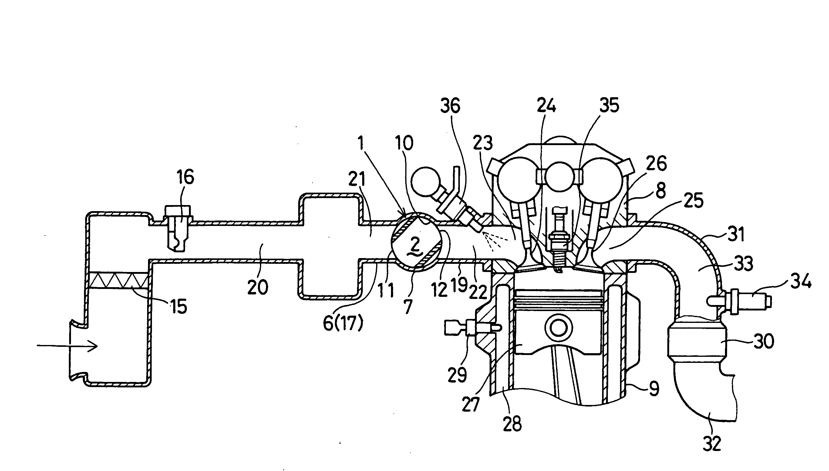
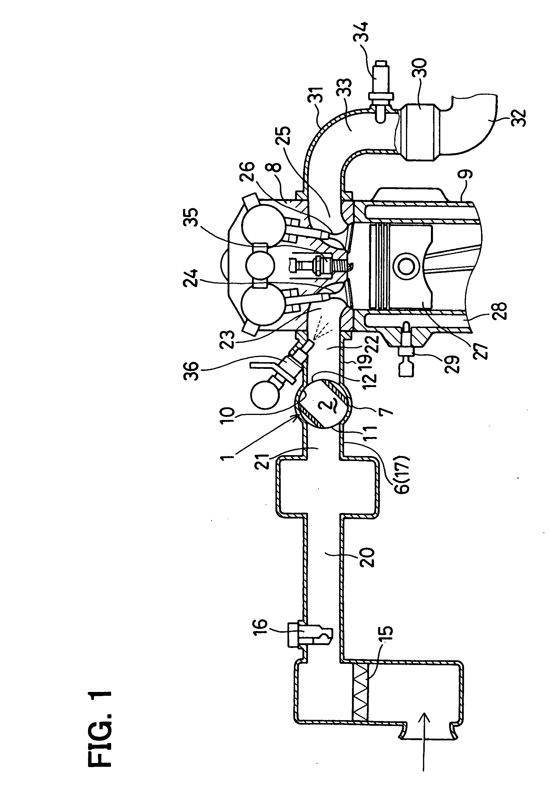
[0063]FIGS. 1 to 3E show the present invention. FIG. 1 is a diagram showing an intake control device for an internal combustion engine. A control device (an engine control system) for an internal combustion engine according to the present embodiment is used as an intake control device for an internal combustion engine equipped with an intake vortex flow generating device. The intake vortex flow generating device can generate an intake vortex flow for promoting a combustion of a mixture gas in each cylinder of a multi-cylinder internal combustion engine (for example, a four-cylinder gasoline engine: hereinafter, referred to as an engine) mounted in an engine compartment of a vehicle such as an automobile.

[0064]The intake control device for the internal combustion engine, or particularly the intake vortex flow generating device, has multiple rotary intake flow control valves (tumble control valves: TCVs) installed respectively for combustion chambers of respective cylinders of the eng...

second embodiment

[0134]Next, the present invention will be described with reference to FIGS. 4A to 4D. FIG. 4A is a diagram showing a state of the fully-closed opening degree where the rotary valve 1 is fully closed. FIGS. 4B to 4D are diagrams each showing a state of the small opening degree where the rotary valve 1 is rotated in a reverse rotational direction.

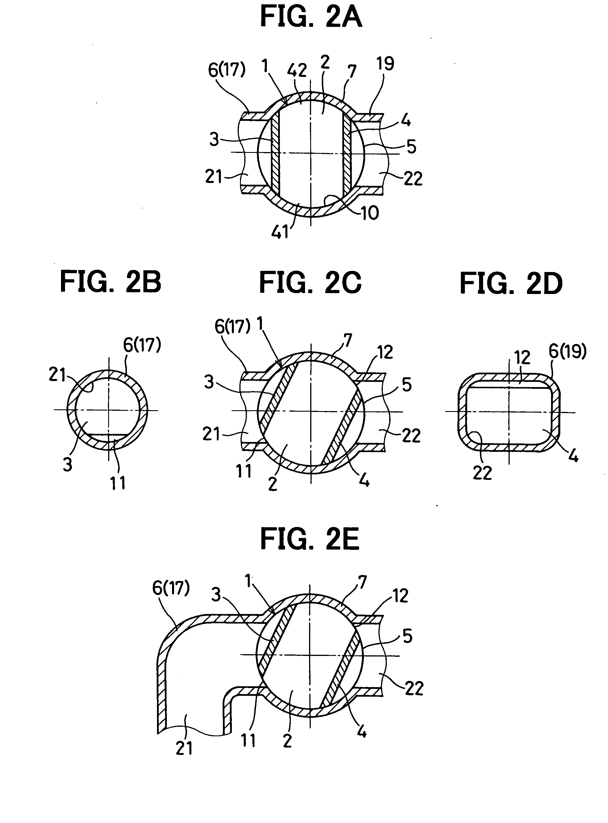
[0135]In the intake vortex flow generating device according to the present embodiment, as shown in FIGS. 4B to 4D, the passage shapes of the intake tube of the engine or particularly the passage shapes of the first and second pipe portions 17, 19 are differentiated such that the passage cross-sectional area of the second intake passage 22 becomes larger than that of the first intake passage 21 when the engine is in the low rotation speed region or the low load region. Specifically, in the present embodiment, the cross-sectional shape of the first intake passage 21 is formed in a circular shape and the cross-sectional shape of the second intak...

third embodiment

[0141]Next, the present invention will be described with reference to FIGS. 5A to 5D. FIG. 5A is a diagram showing a state of a fully-closed opening degree where the rotary valve 1 is fully closed. FIGS. 5B to 5D are diagrams each showing a state of a small opening degree where the rotary valve 1 is open.

[0142]The intake manifold 6 has a second pipe portion 19 (downstream-side flow passage portion) in the shape of a circular pipe downstream of the valve accommodation chamber 10 with respect to the intake flow direction. A second intake passage 22 having a circular cross-sectional shape is formed inside the second pipe portion 19 as shown in FIG. 5D.

[0143]In the intake vortex flow generating device according to the present embodiment, a through bore 14 having an oval cross-sectional shape is formed in the lower portion (in the figure) of the second valve main body 4 as shown in FIGS. 5A, 5C and 5D. The through bore 14 penetrates through the second valve main body 4 to provide communi...


PUM


Abstract

A cross-sectional shape of a first intake passage is formed in a circular shape and a cross-sectional shape of a second intake passage is formed in a rectangular shape. Thus, an opening area of a second intake throttle portion can be made larger than an opening area of a first intake throttle portion even when the opening area of the first intake throttle portion is narrow and an intake air quantity supplied into a combustion chamber of an engine is small as in the case of engine start-up or engine idling operation. Accordingly, an intended strong tumble flow in accordance with a demand for improving a combustion efficiency in the combustion chamber can be generated in the combustion chamber while achieving the intake air quantity necessary during the engine start-up or the engine idling operation.

Description

CROSS REFERENCE TO RELATED APPLICATION[0001]This application is based on and incorporates herein by reference Japanese Patent Application No. 2007-133343 filed on May 18, 2007.BACKGROUND OF THE INVENTION[0002]1. Field of the Invention[0003]The present invention relates to an intake device for an internal combustion engine for supplying intake air into a combustion chamber of the internal combustion engine. In particular, the present invention relates to an intake device of an internal combustion engine having a rotary tumble control valve generating a tumble flow in a combustion chamber of the internal combustion engine.[0004]2. Description of Related Art[0005]As shown in FIGS. 12A to 12E, there is conventionally a known intake device for an internal combustion engine having a rotary tumble control valve (or rotary throttle valve) generating a tumble flow in a combustion chamber of the internal combustion engine (for example, refer to Patent document 1: JP-A-2005-054603 or Patent do...

Claims


Application Information

Patent Timeline
Patent Type & Authority Applications(United States)
IPC IPC(8): F02M35/104F02D9/08
CPCF02D9/16Y02T10/146Y02T10/12
Inventor KOMIYAMA, TADASHIOSUMI, NAOKI
Owner DENSO CORP
Why Eureka
Try Eureka