Variable Compression Ratio Internal Combustion Engine

a compression ratio and internal combustion engine technology, applied in combustion engines, fuel systems, electric control, etc., can solve the problems of fixed compression ratio of internal combustion engines, inability to optimize compression ratios, and difficulty in achieving sufficient engine performance with both fuels, and achieve excellent engine performan

Inactive Publication Date: 2008-01-31
TOYOTA JIDOSHA KK
View PDF2 Cites 45 Cited by
  • Summary
  • Abstract
  • Description
  • Claims
  • Application Information

AI Technical Summary

Benefits of technology

[0004] The present invention has been made taking into consideration the above-described prior arts. The present invention is directed to a variable compression ratio internal combustion engine in which the compression rati

Problems solved by technology

However, in such bi-fuel systems, the compression ratio of the internal combustion engine is fixed, and optimization of the compression ratio has not been done for both the case whe

Method used


Image

  • Variable Compression Ratio Internal Combustion Engine
  • Variable Compression Ratio Internal Combustion Engine
  • Variable Compression Ratio Internal Combustion Engine

Examples


first embodiment

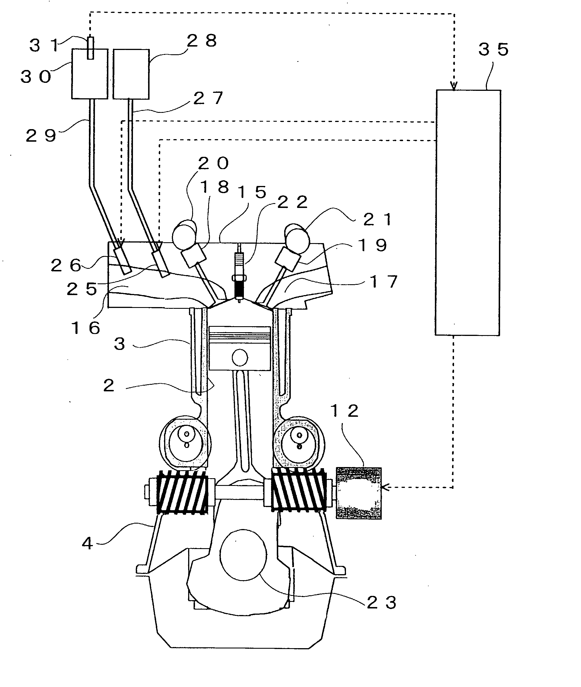
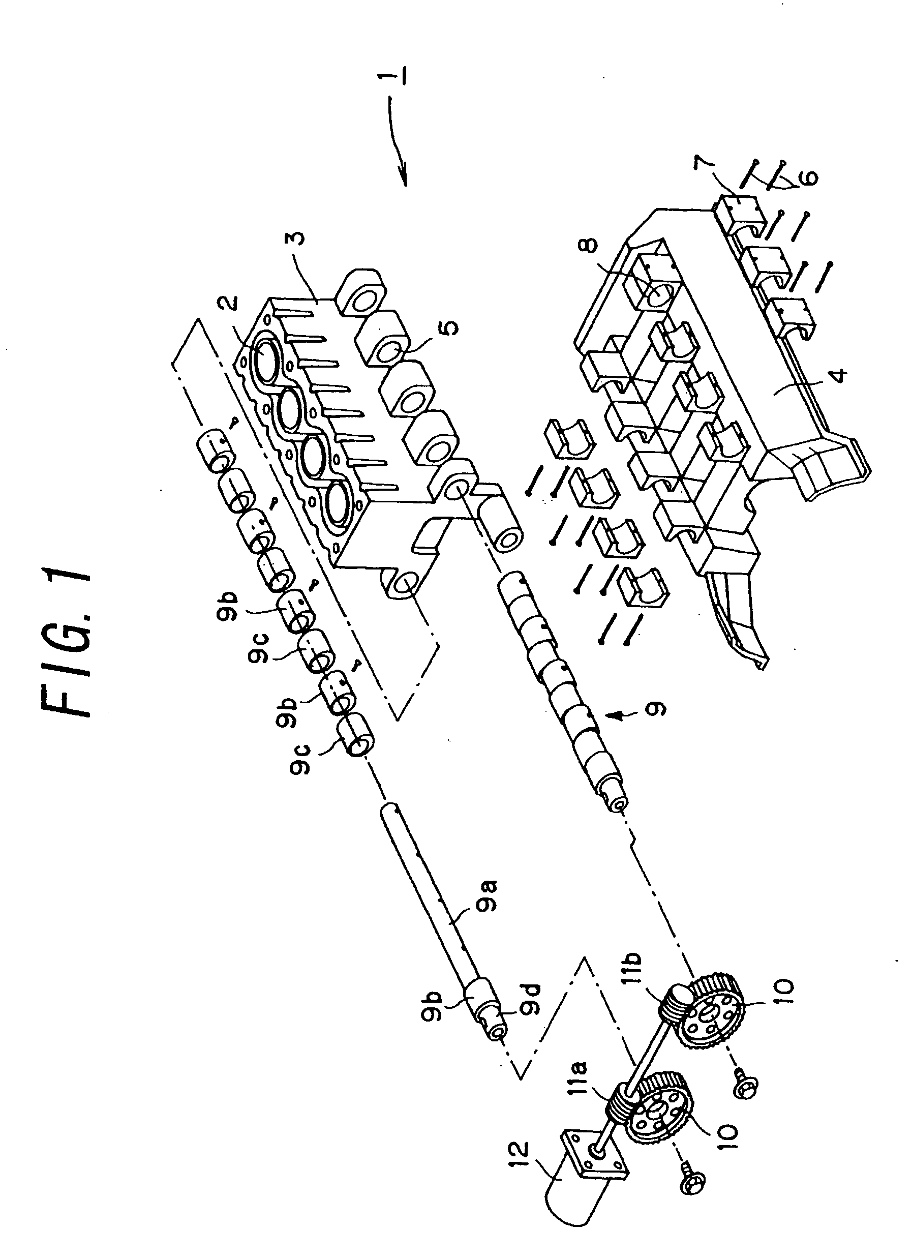
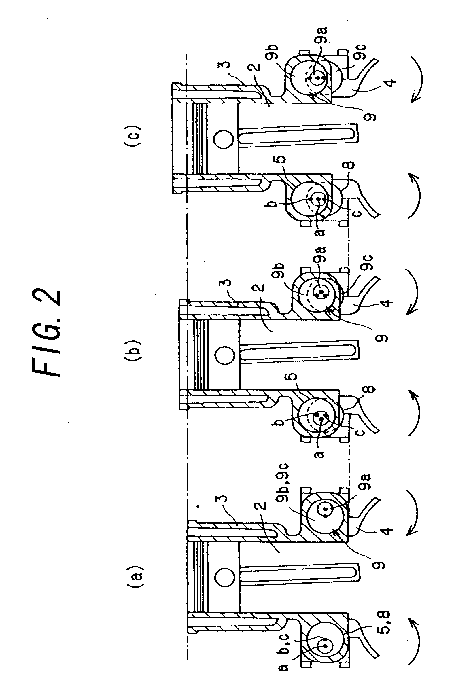
[0044] The internal combustion engine 1 that will be described in the following is a variable compression ratio internal combustion engine, in which the compression ratio is changed by displacing a cylinder block 3 having cylinders 2, along the direction of center axes of the cylinders 2, relative to a crankcase 4 to which pistons are linked.

[0045] First, the structure of the variable compression ratio internal combustion engine according to this embodiment will be described with reference to FIG. 1. As shown in FIG. 1, the cylinder block 3 has a plurality of projecting portions formed on both the lower sides thereof. Each projecting portion has a bearing receiving bore 5 formed therein. The bearing receiving bore 5 is cylindrical in shape and extending perpendicularly to the axial direction of the cylinders 2 and parallel to the direction of arrangement of the multiple cylinders 2. The bearing receiving bores 5 on one side are arranged coaxially, and a pair of axes of the bearing ...

second embodiment

[0079] In the following, the second embodiment of the present invention will be described. In the second embodiment, a description will be made of compression ratio control in the case of the internal combustion engine 1 that is equipped with a direct-injection fuel injection valve for hydrogen 33 for injecting hydrogen as fuel directly into the cylinder 2 in addition to a fuel injection valve for hydrogen 26 for injecting hydrogen as fuel into the intake port 16.

[0080]FIG. 7 is a cross sectional view showing the detailed structure of the internal combustion engine 1 according to the present invention. In this embodiment, a direct-injection fuel injection valve for hydrogen 33 is provided on the top wall of the combustion chamber of the internal combustion engine 1. The direct-injection fuel injection valve for hydrogen 33 is connected with a direct injection hydrogen supply pipe 34. The other end of the direct injection hydrogen supply pipe 34 is connected to a hydrogen supply pip...

third embodiment

[0087] In the following, the third embodiment of the present invention will be described. In the third embodiment, a description will be made of a control in which when the internal combustion engine 1 uses hydrogen as fuel and the amount of NOx emission from the internal combustion engine 1 is larger than a limit NOx emission amount, the air-fuel ratio is made leaner or richer depending on the air-fuel ratio of the internal combustion engine 1 at that time and the compression ratio is decreased to reduce the NOx emission amount. The detailed structure of the internal combustion engine 1 is the same as that shown in FIG. 3, and therefore a description thereof will be omitted.

[0088]FIG. 8 is a graph showing relationship between the air-fuel ratio in the internal combustion engine 1 and the NOx emission amount when hydrogen is used as fuel. As shown in FIG. 8, when hydrogen is used as fuel, as the air-fuel ratio changes from the lean side to the rich side, the NOx emission amount inc...


PUM


Abstract

The invention is directed to a variable compression ratio internal combustion engine in which the compression ratio of the engine can be varied and multiple types of fuels having different combustion velocities are used. The invention provides a technology for achieving excellent engine performance for respective types of fuels. In the variable compression ratio internal combustion engine in which the compression ratio can be varied and multiple types of fuels having different combustion velocities are injected through multiple fuel injection valves, maps from which a target compression ratio of the internal combustion engine is read out are switched in accordance with the fuel used, thereby suppressing knocking or other disadvantages.

Description

TECHNICAL FIELD [0001] The present invention relates to a variable compression ratio internal combustion engine in which the compression ratio of the engine can be varied, and in particular to one that uses multiple types of fuels having different combustion velocities. BACKGROUND ARTS [0002] In recent years, for the purpose of improving gas mileage, power and other performance capabilities of internal combustion engines, technologies for making the compression ratio of an internal combustion engine variable have been proposed. In an already-proposed technology disclosed for example in Japanese Patent Application Laid-Open Nos. 7-26981 and 2003-206771, the cylinder block and the crankcase are linked in such a way as to be movable relative to each other and a cam shaft is provided in their link portion to move the cylinder block and the crankcase toward / away from each other with turning of the cam shaft. [0003] On the other hand, internal combustion engines that use hydrogen as fuel ...

Claims


Application Information

Patent Timeline
IPC IPC(8): F02B69/00
CPCF02B69/02F02D19/0692F02B2201/064F02B2275/14F02B2275/16F02D15/04F02D19/0628F02D35/023F02D37/02F02D41/0025F02D41/3094F02D2250/36Y02T10/36Y02T10/123F02D19/061F02D19/0615F02D19/0644F02D19/0689F02B75/041Y02T10/12Y02T10/30
Inventor KAMIYAMA, EIICHI
Owner TOYOTA JIDOSHA KK
Why Eureka
Try Eureka