Adjustable glass grip

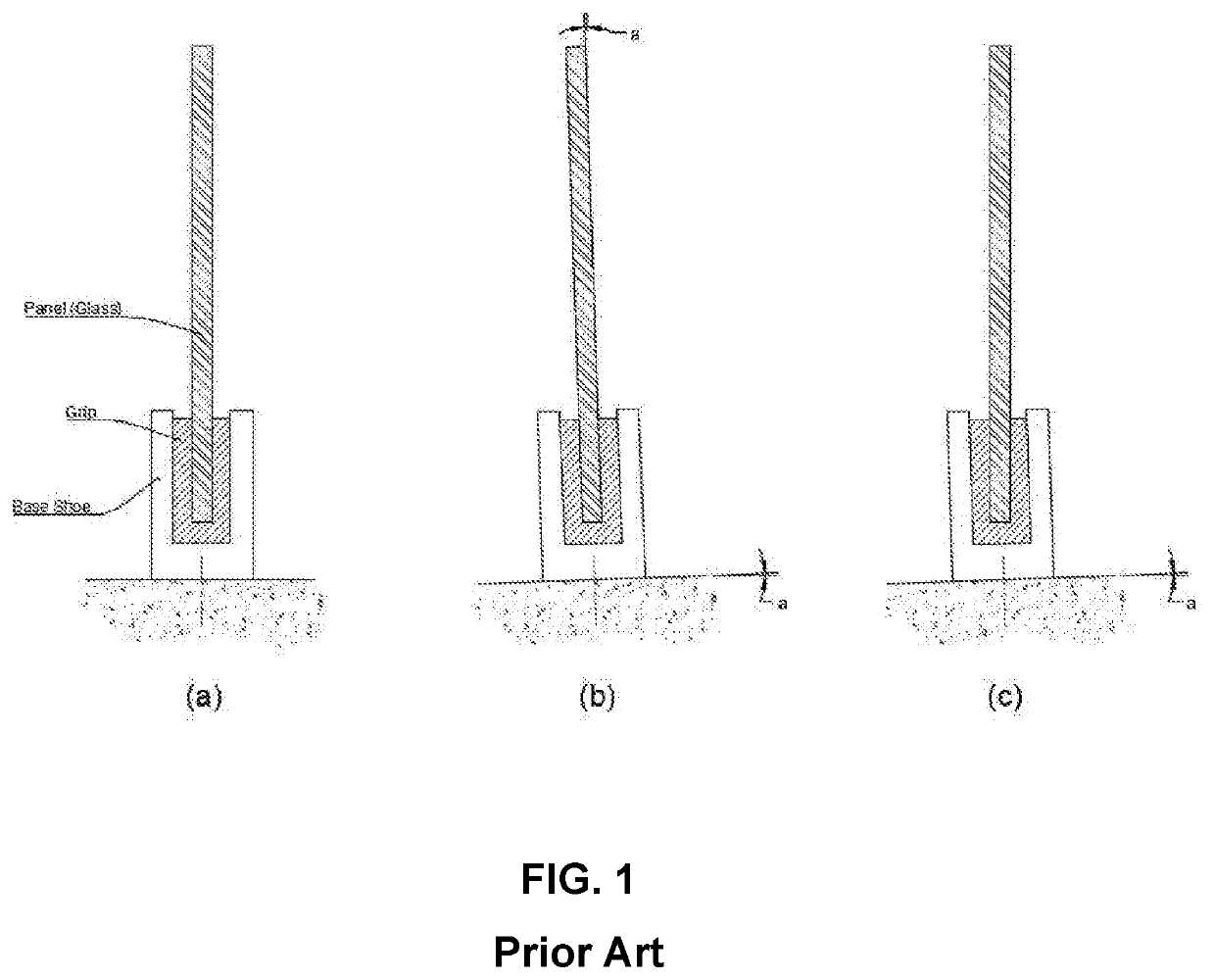
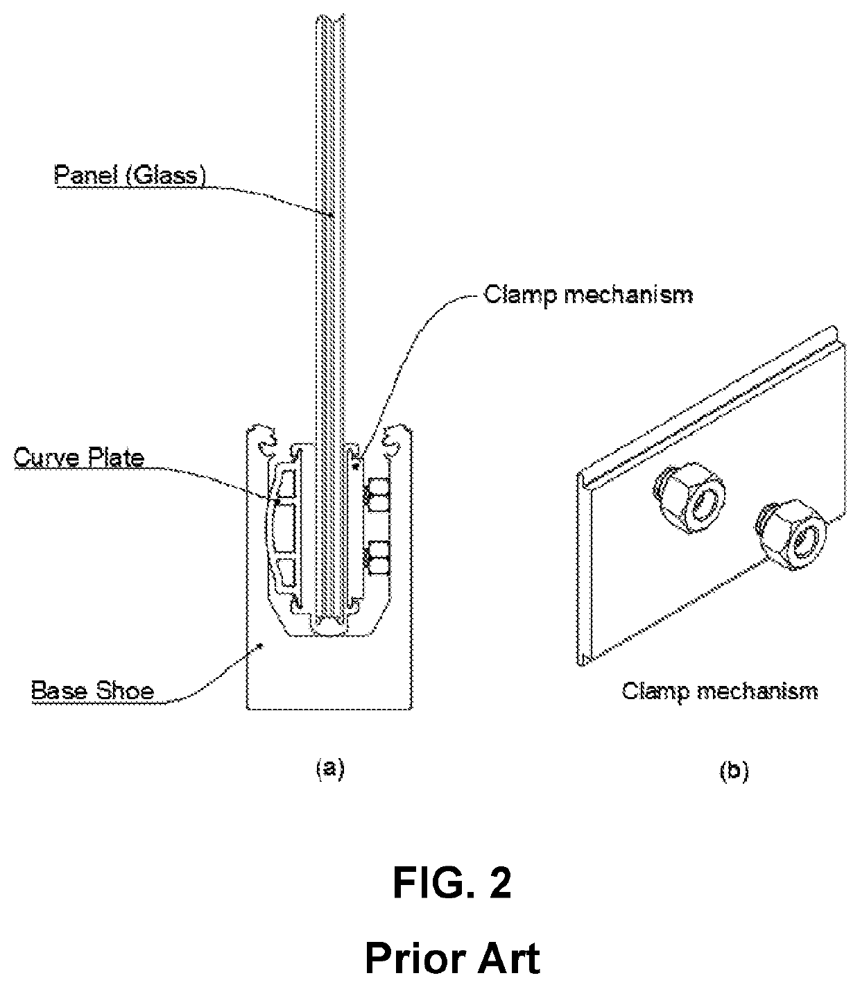
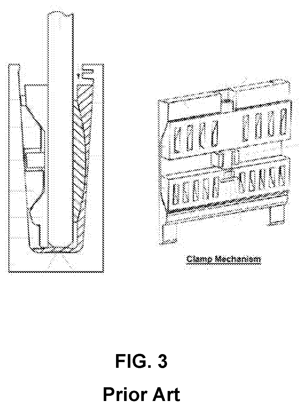
a technology of glass grips and wedges, which is applied in the direction of sheet joining, fastening means, building constructions, etc., can solve the problems of wedges not being able to adjust themselves with the surface of the base shoe, panels not being able to remain vertical,

Active Publication Date: 2020-03-19
EURO ORNAMENTAL FORGINGS
View PDF0 Cites 12 Cited by
  • Summary
  • Abstract
  • Description
  • Claims
  • Application Information

AI Technical Summary

Benefits of technology

[0019]The present Invention is an adjustable clamping system for glass panels installed into a base shoe. The present invention provides adjustability, rigidity, and reliability for a grip to secure a glass. A clamp mechanism is provided that has two wedges, equipped with individual screws, and have a long linear contact area with a base shoe, which makes the clamp mechanism adjustable and reliable. The present invention comprises of two-piece curved plates with parallel surfaces having a wide internal contact area. A concave plate is engaged with the base shoe by a groove at the top.
[0020]The present Invention is more stable in terms of making panels more rigid by:

Problems solved by technology

When the substrate on which the base shoe is being installed is not levelled properly, the panel will not be able to remain vertical (FIG. 1(b)).
While the glass is being installed, the glass grips secured within the base shoe do not remain open by themselves so, putting a piece of glass panel into the glass grips is not easy.
Therefore, when the glass tilts, wedges cannot adjust themselves with the surface of the base shoe.
This system has one central fastener on the wedge side that reduces the reliability of the total system.

Method used


Image

  • Adjustable glass grip
  • Adjustable glass grip
  • Adjustable glass grip

Examples


Embodiment Construction

[0036]The figures are not intended to be exhaustive or to limit the present invention to the precise form disclosed. It should be understood that the invention can be practiced with modification and alteration, and that the disclosed technology be limited only by the claims and equivalents thereof.

[0037]The invention disclosed herein, in accordance with one or more various embodiments, is described in detail with reference to the following figures. The drawings are provided for purposes of illustration only and merely depict typical or example embodiments of the disclosed technology. These drawings are provided to facilitate the reader's understanding of the disclosed technology and shall not be considered limiting of the breadth, scope, or applicability thereof. It should be noted that for clarity and ease of illustration these drawings are not necessarily made to scale.

[0038]An adjustable clamping system 100 for mounting a glass balustrade 200 is shown in FIGS. 5 and 6. An adjusta...


PUM


Abstract

The present invention is an adjustable clamping system for mounting a glass balustrade. The adjustable clamping system comprises of a base shoe with a U-shaped channel, a first L-shaped plate, a second L-shaped plate and a third L-shaped plate which a tilting mechanism sits on the short-upright arm and the long-upright arm is engaged to the glass balustrade from an outside and to the tilting mechanism from an inside. The tilting mechanism comprises of a first-block and a second-cube, an L-shaped block at the bottom, and two wedge parts between the L-shaped block and the first-block and the second-cube, and wherein the first-cube, the second-block and the L-shaped block connected together by two socket screws, by turning the socket screws, two wedge parts at a top portion and a bottom portion of the tilting mechanism move to the right and left and push to the right-side wall of the base shoe to adjust the glass balustrade.

Description

RELATED APPLICATION[0001]The present invention claims the priority date of the provisional patent application No. 62 / 733,392 filed on Sep. 19, 2018.FIELD OF THE INVENTION[0002]The present invention pertains generally to a device to hold cantilever panels, and especially to support glass balustrades.BACKGROUND OF THE INVENTION[0003]Cantilever glass panels (typically used as guards or partitions) have two main components: a base shoe and a grip to hold the glass panel as shown in FIG. 1(a). The base shoe is basically a U-channel secured to a substrate, and the grips is a specific clamp that is secured within the base shoe to hold the panels in place. When the substrate on which the base shoe is being installed is not levelled properly, the panel will not be able to remain vertical (FIG. 1(b)).[0004]The key feature of the present invention is to provide an angular backward and forward adjustability for the panel. Therefore, in the event of installing the base shoe on a slope, the grip ...

Claims


Application Information

Patent Timeline
Patent Type & Authority Applications(United States)
IPC IPC(8): E04F11/18F16B2/06
CPCF16B2/065E04F2011/1895E04F11/1812E04F11/1853F16B2/14F16B5/0614
Inventor RAVAN, ALIMERCIECA, HENRY
Owner EURO ORNAMENTAL FORGINGS
Why Eureka
Try Eureka