
Self-Tapping Screw With Stop Flange That is Formed by Threading Die

Inactive Publication Date: 2020-04-16
CHEN WEI CHIH
View PDF0 Cites 2 Cited by
  • Summary
  • Abstract
  • Description
  • Claims
  • Application Information

AI Technical Summary

Benefits of technology

The present invention provides a self-tapping screw with an external thread and a stop flange integrally formed with the shank, which prevents excessive wear and breakage during operation. The invention achieves this by simultaneously threading and squeezing the rotating shank using two threading dies, which results in a stronger and more durable screw.

Problems solved by technology

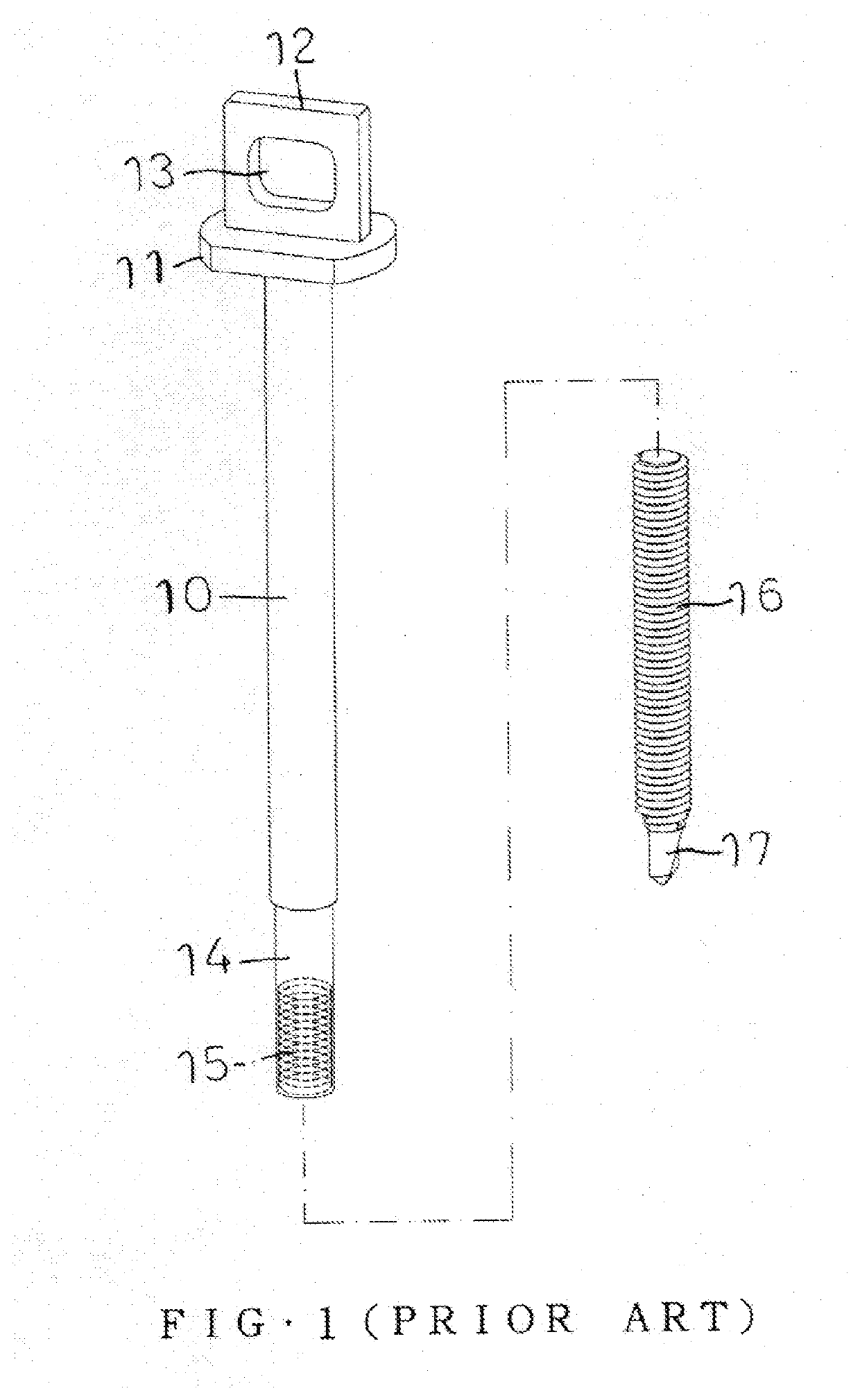
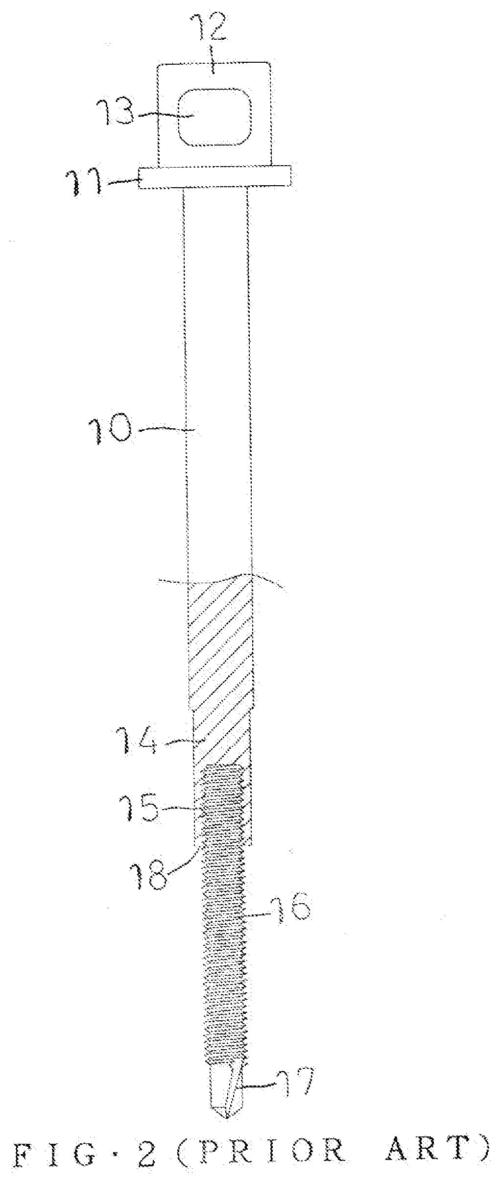
However, the headless screw 16 is easily fed and locked excessively due to an undue working, an erroneous assembly process or improper operation of the user, so that the headless screw 16 is easily worn out or broken during operation.
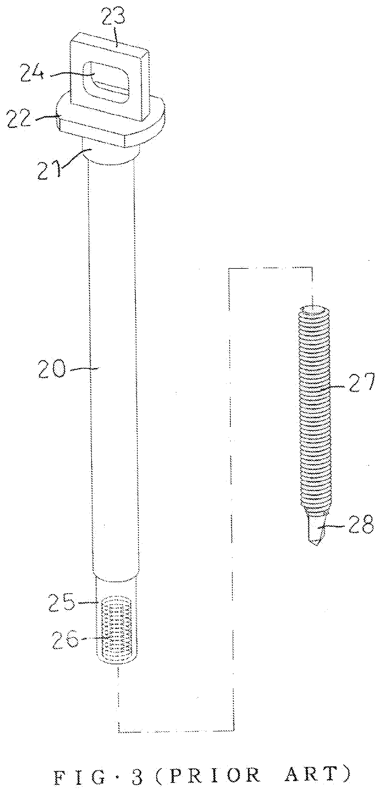
However, the headless screw 27 is easily fed and locked excessively due to an undue working, an erroneous assembly process or improper operation of the user, so that the headless screw 27 is easily worn out or broken during operation.

Method used


Image

  • Self-Tapping Screw With Stop Flange That is Formed by Threading Die
  • Self-Tapping Screw With Stop Flange That is Formed by Threading Die
  • Self-Tapping Screw With Stop Flange That is Formed by Threading Die

Examples


Embodiment Construction

[0031]Referring to the drawings and initially to FIGS. 5 and 6, a self-tapping screw in accordance with the preferred embodiment of the present invention comprises a shank 30 having a rear end provided with a drilling tip 37 and an external thread 36. The external thread 36 has a top formed with a stop flange 34 to stop a further movement of the external thread 36. The stop flange 34 has a diameter greater than that of the external thread 36. The stop flange 34 has a bottom provided with a flat face 341 and a top provided with a conic face 342. The stop flange 34 has a position that is adjusted according to the thickness of a workpiece. The shank 30 is provided with a groove 35 located above the stop flange 34. The shank 30 has a front end provided with a fixing plate 31 disposed horizontally. The fixing plate 31 has a top provided with a rotation head 32 disposed vertically. Preferably, the rotation head 32 is a sheet plate and provided with a through hole 33. Thus, the rotation he...


PUM


Abstract

A self-tapping screw includes a shank having a rear end provided with a drilling tip and an external thread. The external thread has a top formed with a stop flange. The stop flange has a diameter greater than that of the external thread. Thus, the shank is integrally formed with the stop flange by two threading dies, to stop a further movement of the external thread, and to prevent the external thread from being fed and locked excessively, thereby preventing the shank from being worn out or broken during operation.

Description

BACKGROUND OF THE INVENTION1. Field of the Invention[0001]The present invention relates to a screw and, more particularly, to a self-tapping screw.2. Description of the Related Art[0002]A first conventional self-tapping screw in accordance with the prior art shown in FIGS. 1 and 2 comprises a shank 10 and a headless screw 16 connected with the shank 10. The shank 10 has a front end provided with a fixing plate 11 disposed horizontally. The fixing plate 11 has a top provided with a rotation head 12 disposed vertically. The rotation head 12 is provided with a through hole 13. Thus, the rotation head 12 is rotated by a driving tool to rotate the shank 10. The shank 10 has a rear end provided with a mounting tube 14 which has an interior provided with an internal thread 15. The headless screw 16 is screwed into the internal thread 15 of the mounting tube 14 and has a rear end provided with a tip 17. A stepped face 18 is defined between the mounting tube 14 and the headless screw 16. The...

Claims


Application Information

Patent Timeline
IPC IPC(8): F16B25/10F16B25/00
CPCF16B25/0084F16B25/0078F16B25/103F16B25/0021F16B25/0031F16B25/0063
Inventor CHEN, WEI-CHIH
Owner CHEN WEI CHIH
Learn More