Axial fan with tip fences

Pending Publication Date: 2019-08-01
CARRIER CORP
View PDF0 Cites 5 Cited by
  • Summary
  • Abstract
  • Description
  • Claims
  • Application Information

AI Technical Summary

Benefits of technology

The patent describes an axial flow fan used in a refrigerated display cabinet to circulate air. The fan includes a hollow casing with a diameter that increases towards the outlet end. The fan also includes a hub and a plurality of fan blades that extend from the hub to a blade tip. The blade tip of each fan blade has a greater diameter than the thickness of the fan blade. The fan also has a tip fence that extends beyond the blade tip and the fence remains constant in thickness. The fan can be mounted in the refrigerated display cabinet and the hub and fan blades can be integrally formed or separately formed and then coupled together. The technical effects of the patent include an improved air circulation system that helps to keep the product display area cool and a more efficient fan design that reduces noise and improves air flow.

Problems solved by technology

Although the display case has a relatively low pressure duty requirement, the path of the air provided to the evaporator fan is torturous and includes multiple 90 degree turns and downstream obstructions.
Accordingly, integration of axial fan without affecting both performance and noise of the merchandiser can be challenging.

Method used


Image

  • Axial fan with tip fences
  • Axial fan with tip fences
  • Axial fan with tip fences

Examples


embodiment 1

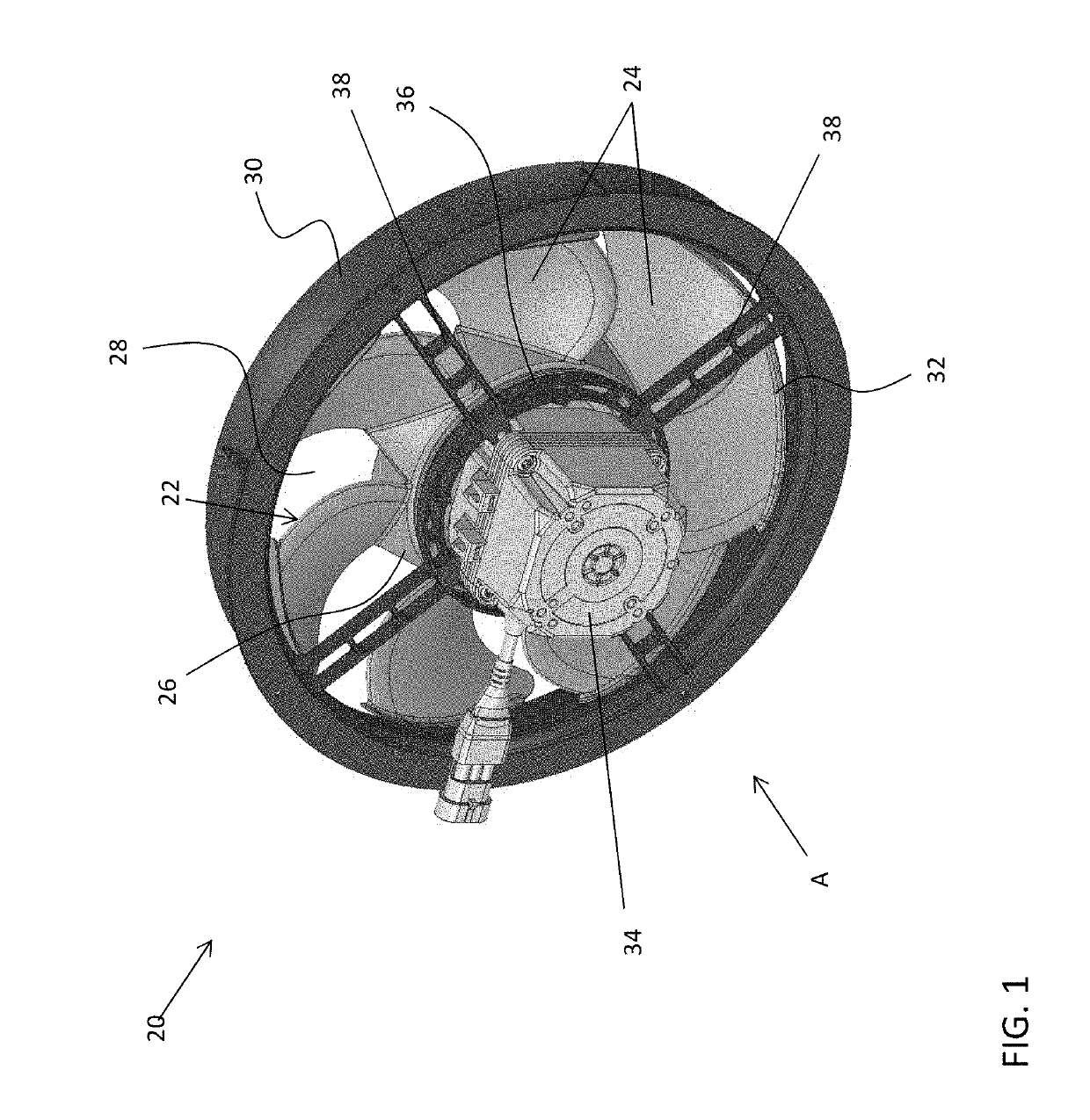
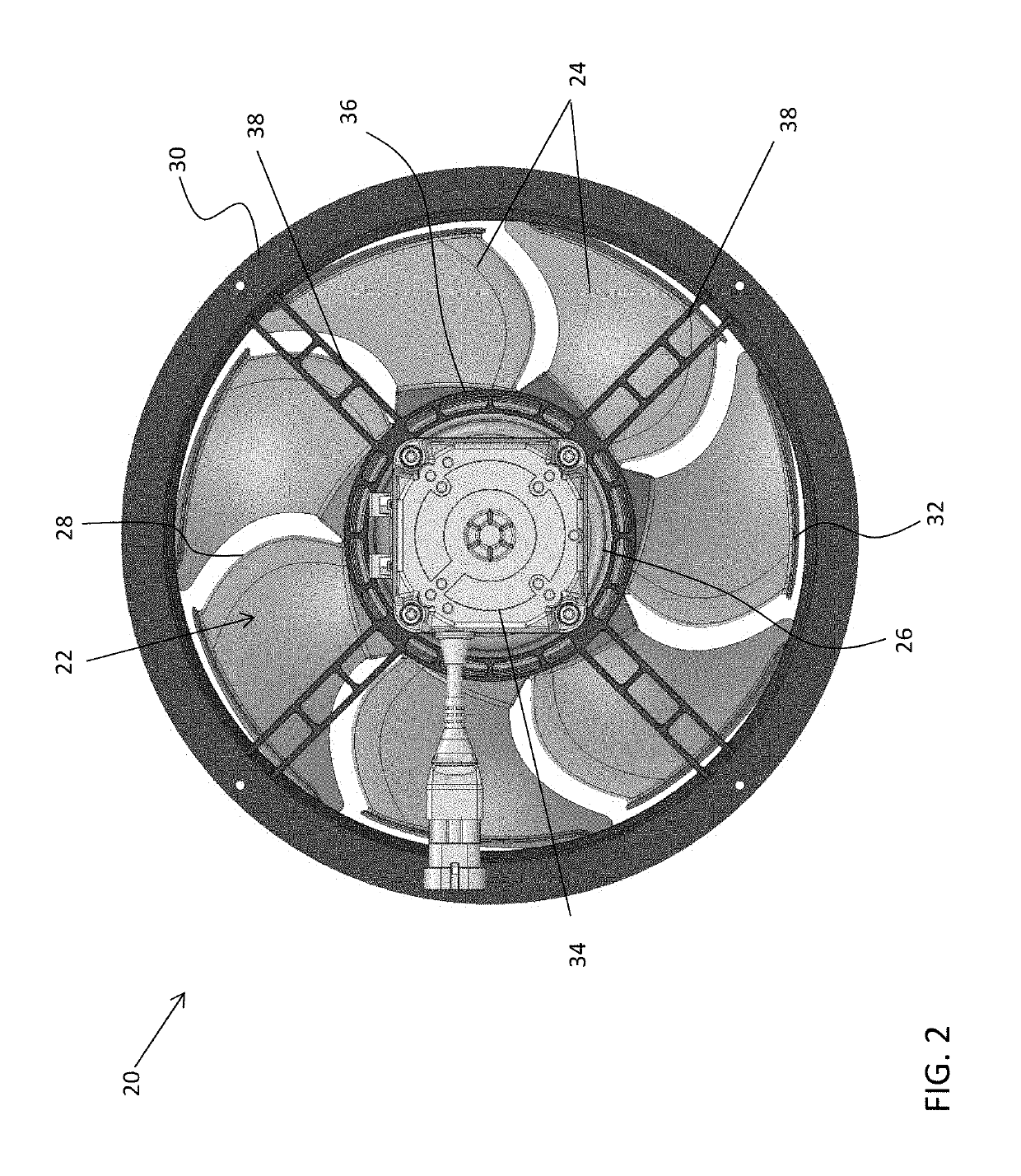
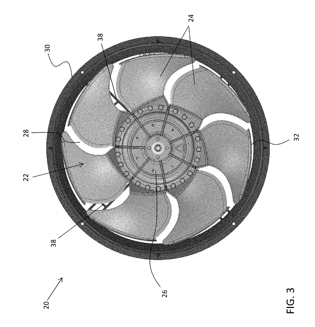
[0050]An axial flow fan comprising: a generally hollow casing defining an inlet end and an outlet end of the axial flow fan, wherein a diameter of the casing increases from the inlet end to the outlet end; an impeller rotatably mounted within the casing, the impeller including: a hub; a plurality of fan blades extending from a root at the hub to a blade tip, wherein a diameter of the blade tip of each of the plurality of fan blades increases from the inlet end to the outlet end; and a tip fence located at the blade tip of at least one of the plurality of fan blades, wherein a length of the tip fence measured perpendicular to the fan blades is greater than a thickness of the at least one of the plurality of fan blades.

embodiment 2

[0051]The axial flow fan of embodiment 1, wherein an axial clearance, measured parallel to the diameter of the casing, is defined between the tip fence of each of the plurality of fan blades and an adjacent surface of the casing and the axial clearance remains constant between the inlet end and the outlet end of the axial flow fan with a tolerance of + / −1 mm.

embodiment 3

[0052]The axial flow fan of embodiment 1, wherein an outer diameter of the hub increases from the inlet end to the outlet end.


PUM


Abstract

An axial flow fan includes a generally hollow casing defining an inlet end and an outlet end of the axial flow fan. A diameter of the casing increases from the inlet end to the outlet end. An impeller is rotatably mounted within the casing. The impeller includes a hub and a plurality of fan blades extending from a root located at the hub to a blade tip. A diameter of the blade tip of each of the plurality of fan blades increases from the inlet end to the outlet end. A tip fence is located at the blade tip of at least one of the plurality of fan blades and a length of the tip fence measured perpendicular to the fan blades is greater than a thickness of the at least one of the plurality of fan blades.

Description

CROSS-REFERENCE TO RELATED APPLICATIONS[0001]This application claims the benefit of U.S. Provisional Application Ser. No. 62 / 624,483 filed Jan. 31, 2018, which is incorporated herein by reference in its entirety.BACKGROUND[0002]Embodiments of the present disclosure generally relate to a refrigerated display merchandiser, and more particularly, to a fan assembly for use in a refrigerated display merchandiser where food and / or beverages are displayed.[0003]Typically, supermarkets and convenient stores are equipped with display cases or merchandisers, which may be open or provided with doors, for presenting fresh food or beverages to customers, while maintaining the fresh food and beverages in a refrigerated environment. The refrigeration systems of such merchandisers commonly employ a conventional refrigeration cycle and include an evaporator and evaporator fan operatively associated with the refrigerated interior of the cabinet, as well as a condenser, a condenser fan, and compressor...

Claims


Application Information

Patent Timeline
IPC IPC(8): F04D29/38F04D19/00A47F3/04
CPCF04D29/384F04D19/002A47F3/0447F04D29/325F04D29/329F04D29/388F04D29/666A47F3/0408F04D29/547F05D2240/307F01D11/08F05B2240/11F01D5/143F01D5/20
Inventor DYGERT, RYAN K.
Owner CARRIER CORP
Why Eureka
Try Eureka