
Bit puller

a bit puller and bit technology, applied in the field of bit pullers, can solve the problems of affecting the workpiece, affecting the workpiece, and not working for very stuck drill bits,

Active Publication Date: 2020-05-07
THE BOEING CO
View PDF0 Cites 0 Cited by
  • Summary
  • Abstract
  • Description
  • Claims
  • Application Information

AI Technical Summary

Benefits of technology

[0006]The embodiments allow a method for extraction of a drill bit wherein a drill bit is engaged in an attachment mechanism internal to an inner element. An outer element having internal threads is received on external threads on the inner element. The inner element is then rotated with respect to the outer element urging a foot portion of the outer element into contact with a workpiece and withdrawing the inner element on a longitudinal axis thereby extracting the drill bit.

Problems solved by technology

This may be due to the bit dulling, removed material clogging the hole, or other situations.
The drill motor can be run in reverse to back the drill bit out, but this may not work for very stuck drill bits (especially, where the removed material jams the flutes of the drill bit).
A prying device, such as a claw hammer or pry bar, can be used to pull the drill bit from the workpiece, but these devices pull the drill bit off center during removal, which may damage or alter the hole or workpiece or break the drill bit off in the workpiece.
Often, attempted extraction with the drill motor or other machine tool may fracture the bit or damage the workpiece.
The bit may become stuck at any depth which complicates removal since a normal collet attachment to the bit requires attachment proximate the end of the shaft which may be spaced from the workpiece allowing undesirable bending torque to be exerted on the bit increasing the likelihood of fracturing the bit.
These screws may be difficult to access depending on where the drill bit is or may be time consuming to tighten and loosen.
Further, the tools are fairly complicated because they include several different components that need to work together to attach to the drill bit and to pull the drill bit from the workpiece.

Method used


Image

  • Bit puller
  • Bit puller
  • Bit puller

Examples


Embodiment Construction

[0017]The embodiments described herein provide a method and tool for operation to allow removal of drill bits, which may engage the bit at any drill depth. Further, the system is self-engaging for ease in removing the bit.

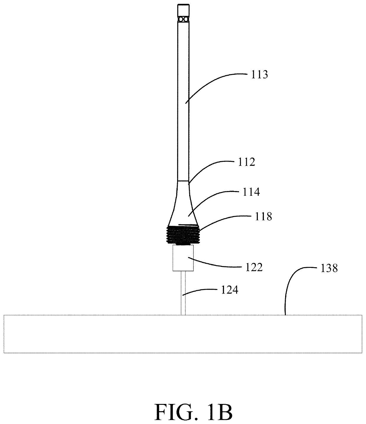
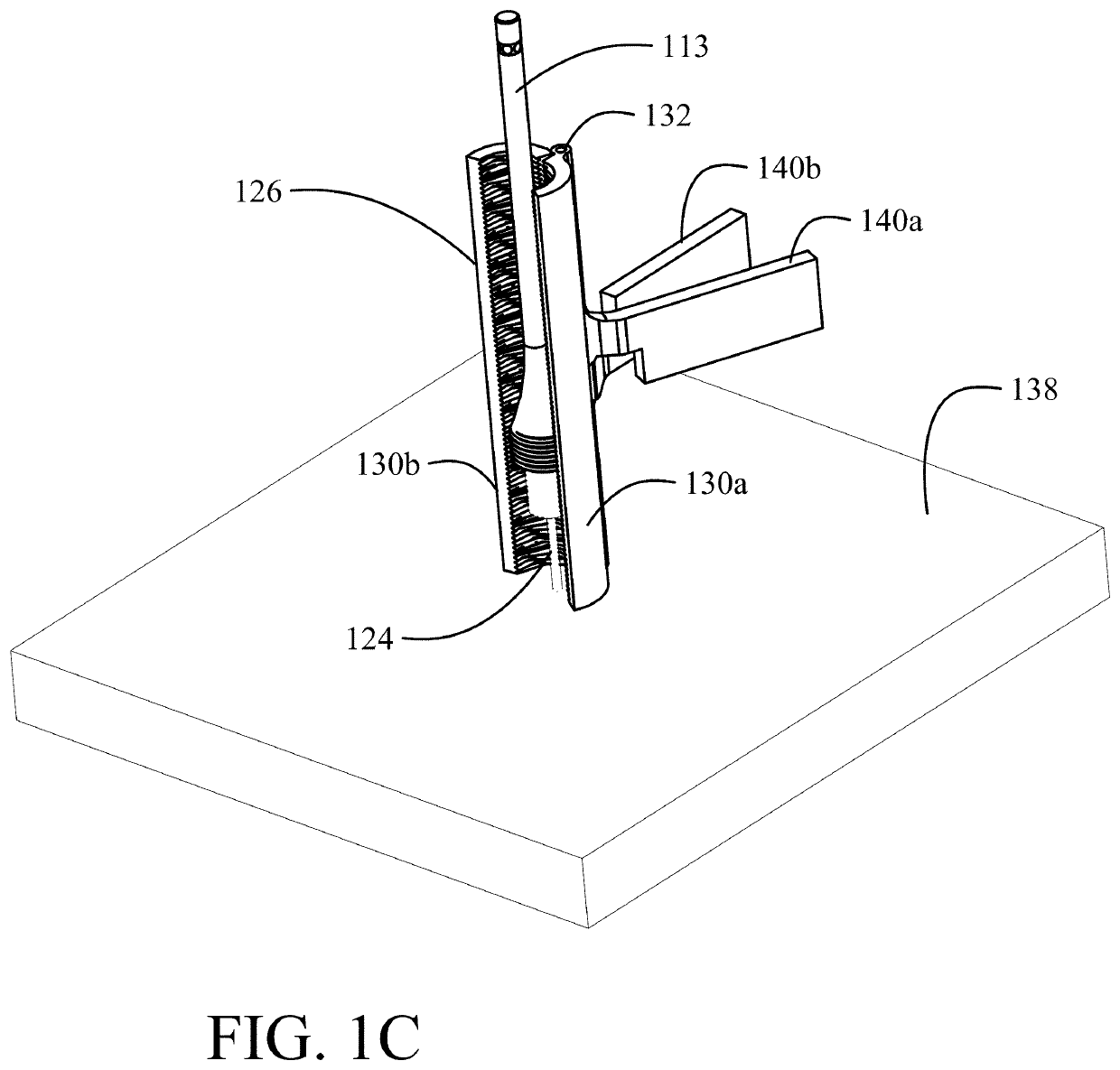
[0018]Embodiments disclosed herein provide a bit puller having an inner element adapted to engage the drill bit and having an external threaded surface. The inner element includes a drive connection for rotation of the inner element. An outer element has an internal thread adapted to concentrically engage the external threaded surface of the inner element at an adjustable height whereby the drill bit may be engaged by the inner element at any depth of penetration at which binding has occurred. The outer element has a foot portion engaging the workpiece concentrically surrounding the drill bit. Rotation of the inner element with the drive connection rotates the outer threads of the inner element within the inner threads of the outer element to withdraw the inner ele...


PUM


Abstract

A bit puller incorporates an inner element with a longitudinal axis and having a central shaft, a base with external threads and an engagement mechanism internal to the inner element adapted to engage a drill bit. An outer element is concentric with the inner element and has a foot portion for engaging a work piece. Internal threads in the outer element are adapted to engage the external threads of the base wherein rotation of the inner element with respect to the outer element withdraws the inner element along the longitudinal axis.

Description

REFERENCE TO RELATED APPLICATIONS[0001]This application is a divisional of U.S. application Ser. No. 15 / 055,988 filed on Feb. 29, 2016, having a common assignee with the present application, the disclosure of which is incorporated herein by reference.BACKGROUND INFORMATIONField[0002]Embodiments of the disclosure relate generally to devices for removing drill bits from a workpiece and more particularly to a system employing an inner element to engage the drill bit and having an externally threaded portion engaged by inner thread on an outer element adapted to engage a surface of the workpiece whereby rotation of the inner element within the outer element withdraws the inner element and bit from the workpiece.Background[0003]Drill bits may bind within a drill bore in a workpiece. This may be due to the bit dulling, removed material clogging the hole, or other situations. The drill motor can be run in reverse to back the drill bit out, but this may not work for very stuck drill bits (e...

Claims


Application Information

Patent Timeline
Patent Type & Authority Applications(United States)
IPC IPC(8): B25B27/18B25B27/02
CPCB25B27/18B25B27/023B23B47/00
Inventor SHEHAB, KAREEM GAMAL
Owner THE BOEING CO
Features
  • Generate Ideas
  • Intellectual Property
  • Life Sciences
  • Materials
  • Tech Scout
  • Unparalleled Data Quality
  • Higher Quality Content
  • 60% Fewer Hallucinations
Learn More