Passive q-switch pulse laser device, processing apparatus, and medical apparatus

a pulse laser and processing apparatus technology, applied in the direction of optical resonator shape and construction, active medium materials, surgery, etc., can solve the problems of increasing the width of the pulse, increasing the length of the optical resonator, and increasing the pulse width, so as to achieve stable polarization direction and increase the pulse width of the pulsed laser light

Active Publication Date: 2020-06-04
SONY CORP
View PDF0 Cites 0 Cited by
  • Summary
  • Abstract
  • Description
  • Claims
  • Application Information

AI Technical Summary

Benefits of technology

[0015]As described above, according to the present disclosure, it is possible to generate pulsed laser light having a stable polarization direction while suppressing an increase in the pulse width of the pulsed laser light and a decrease in the peak intensity of the pulsed laser light, and miniaturizing an optical resonator and a laser device in a case where an amorphous material is used as the base material of a laser medium.
[0016]It should be noted that the above-described effects are not necessarily limitative. Any of the effects indicated in this description or other effects that may be understood from this description may be exerted in addition to the above-described effects or in place of the above-described effects.

Problems solved by technology

However, when the polarizing element is disposed in the optical resonator, the length of the optical resonator increases.
This increases the pulse width (i.e., the time width of the pulse increases), decreases the peak intensity of the laser light, or makes it difficult to miniaturize the optical resonator itself or the laser device.

Method used


Image

  • Passive q-switch pulse laser device, processing apparatus, and medical apparatus
  • Passive q-switch pulse laser device, processing apparatus, and medical apparatus

Examples


Embodiment Construction

[0020]The following describes a preferred embodiment of the present disclosure in detail with reference to the accompanying drawings. It should be noted that, in this description and the accompanying drawings, constituent elements that have substantially the same functional configuration are indicated by the same reference signs, and thus redundant description thereof is omitted.

[0021]It should be noted that the description is given in the following order.

1. Background

2. Overview of Present Embodiment

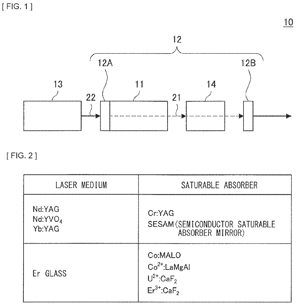
[0022]3. Configuration of Passive Q-Switch Pulse Laser Device according to Present Embodiment

4. Member Used as Polarizing Element

5. Modification

6. Conclusion

1. BACKGROUND

[0023]In recent years, various laser devices have been developed. For example, a Q-switch pulse laser device has been developed. The Q-switch pulse laser device is a laser device that is able to radiate pulsed laser light having energy at a considerable level or more at predetermined intervals. The Q-switch pulse laser ...


PUM

PropertyMeasurementUnit
wavelengthaaaaaaaaaa
transmittanceaaaaaaaaaa

Abstract

[Overview] [Problem to be Solved] To make it possible to generate pulsed laser light having a stable polarization direction while suppressing an increase in the pulse width of the pulsed laser light and a decrease in the peak intensity of the pulsed laser light, and miniaturizing an optical resonator and a laser device in a case where an amorphous material is used as the base material of a laser medium. [Solution] There is provided a passive Q-switch pulse laser device including: a laser medium; and a saturable absorber. The laser medium is disposed between a pair of reflection means included in an optical resonator. The laser medium is excited by specific excitation light to emit emission light. The saturable absorber is disposed on an optical axis of the optical resonator and on a downstream side of the laser medium between the pair of reflection means. The saturable absorber has a transmittance increased by absorption of the emission light. At least one of the pair of reflection means is a polarizing element. The polarizing element has different reflectances with respect to the respective pieces of emission light in polarization directions orthogonal to each other.

Description

TECHNICAL FIELD[0001]The present disclosure relates to a passive Q-switch pulse laser device, a processing apparatus, and a medical apparatus.BACKGROUND ART[0002]In recent years, various laser devices have been developed. For example, a Q-switch pulse laser device has been developed. The Q-switch pulse laser device is a laser device that is able to radiate pulsed laser light having energy at a considerable level or more at predetermined intervals. For example, a passive Q-switch pulse laser device has been actively developed that changes a Q factor with a passive element such as a saturable absorber.[0003]Incidentally, for example, to perform wavelength conversion using a nonlinear optical crystal and shape measurement using linearly polarized light, it is preferable that the polarization direction of laser light given off from a laser device be controlled and stabilized. As a method of controlling the polarization direction of laser light, for example, NPL 1 to 3 below disclose tec...

Claims


Application Information

Patent Timeline
Patent Type & Authority Applications(United States)
IPC IPC(8): H01S3/11H01S3/08A61F9/008
CPCH01S3/1643H01S3/1611A61B2018/20553H01S3/09415H01S3/1115H01S3/08054A61F9/008H01S3/113A61B18/20H01S3/08059H01S3/1685H01S3/17H01S3/0602H01S3/0621
Inventor KAMATA, MASANAOMIZUMURA, SUMITO
Owner SONY CORP
Why Eureka
Try Eureka