Dehumidifying element and dehumidifying device having same

Active Publication Date: 2020-06-11
SMC CORP
View PDF0 Cites 0 Cited by
  • Summary
  • Abstract
  • Description
  • Claims
  • Application Information

AI Technical Summary

Benefits of technology

The invention is a dehumidifying element and a dehumidifying device that uses a cylindrical casing and hollow fiber membranes for effectively removing humidity from the air. The device has guide members that help to evenly distribute the membranes in the dehumidification space, which prevents uneven distribution and ensures better contact between the membranes and the purge air. This prevents a decrease in the efficiency of the dehumidification process.

Problems solved by technology

Accordingly, the hollow fiber membranes that are bent tend to cling to each other and be present unevenly in the dehumidification space of the cylindrical casing, which may cause the purging air to flow unevenly.
In such a state, a sufficient contact area cannot be obtained between the purging air and the hollow fiber membranes, which may degrade the dehumidification efficiency.

Method used


Image

  • Dehumidifying element and dehumidifying device having same
  • Dehumidifying element and dehumidifying device having same
  • Dehumidifying element and dehumidifying device having same

Examples


Embodiment Construction

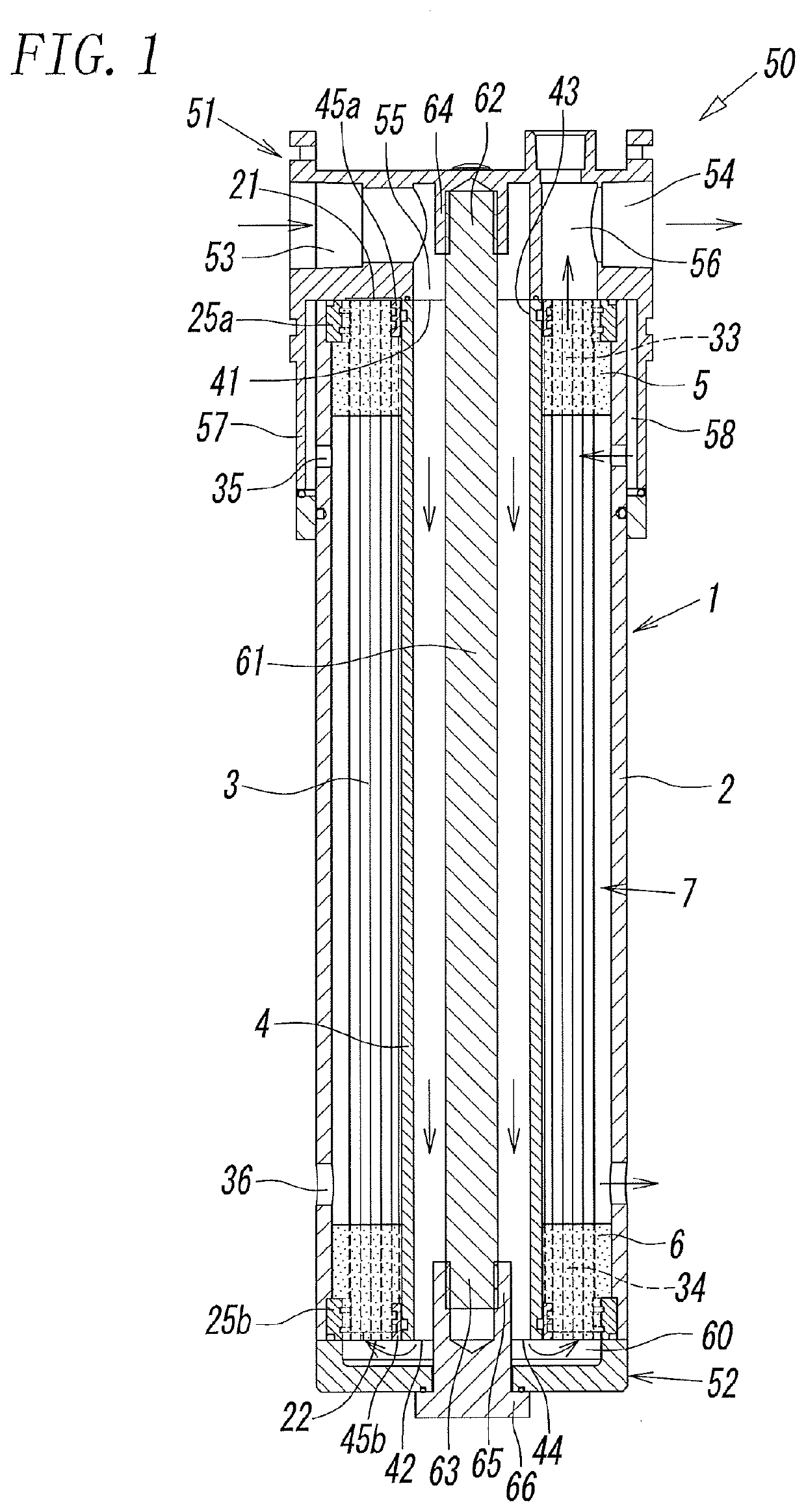
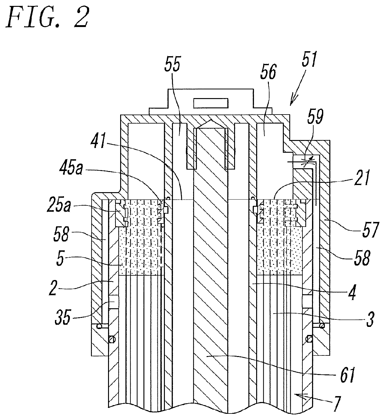
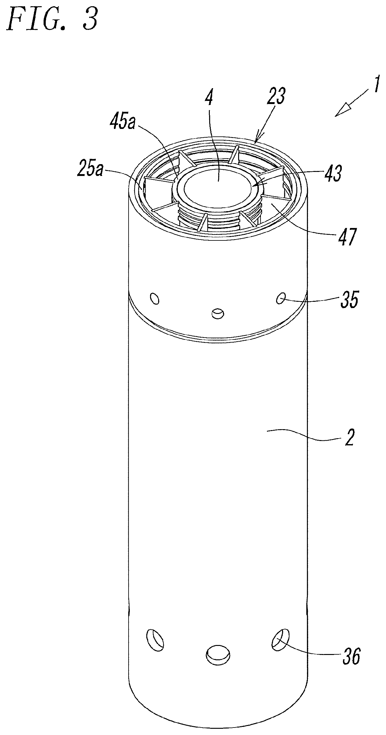
[0021]An embodiment of a dehumidifying element 1 according to the invention and a dehumidifying device 50 having the dehumidifying element 1 will be described with reference to the drawings.

[0022]As illustrated in FIG. 1, the dehumidifying device 50 according to the present embodiment includes the dehumidifying element 1 having hollow fiber membranes 3 for dehumidifying dehumidification-target air and also includes a first capping member 51 and a second capping member 52 that are detachably and airtightly attached to respective opposite ends of the dehumidifying element 1 in the axial direction thereof.

[0023]In the first capping member 51, an inlet channel 55 having an inlet port 53 and an outlet channel 56 having an outlet port 54 are formed. Highly humid dehumidification-target air that is input from the outside to the inlet port 53 is supplied through the inlet channel 55 to the dehumidifying element 1. Dried air that has been dried in the dehumidifying element 1 is output throug...


PUM


Abstract

[Object] To prevent deterioration of dehumidification efficiency by suppressing uneven distribution of hollow fiber membranes in an outer casing.[Solution] A dehumidifying element 1 includes a dehumidification space 7 that are formed between a pair of potting material portions 5 and 6 and that accommodates hollow fiber membranes 3 through which highly humid dehumidification-target air is circulated. The dehumidifying element 1 also includes an air supply hole 35 for supplying purging air having a humidity lower than the dehumidification-target air to the dehumidification space 7 and an air discharge hole 36 for discharging the purging air supplied to the dehumidification space 7. In the dehumidification space 7, a guide member 47 is disposed so as to form a plurality of regions in a cylindrical casing 2 as viewed in the axis-L direction, and the hollow fiber membranes 3 are accommodated in the dehumidification space 7 so as to be distributed into the plurality of regions.

Description

TECHNICAL FIELD[0001]The present invention relates to a dehumidifying element utilizing hollow fiber membranes and also relates to a dehumidifying device including the dehumidifying element.BACKGROUND ART[0002]A known dehumidifying device, which is a device for dehumidifying target air and supplying dehumidified air to a fluid-pressure device or the like, dehumidifies the dehumidification-target air by circulating the target air in the hollow fiber membranes and causing water vapor contained in the dehumidification-target air to pass out through the hollow fiber membranes. The water vapor that has passed out is discharged to the outside by using purging air. As examples of such a dehumidifying device, a Patent Literature 1 (PTL 1) and a Patent Literature 2 (PTL 2) disclose dehumidifying devices that dehumidify dehumidification-target air by circulating the target air in the hollow fiber membranes accommodated in a cylindrical casing of a dehumidifying element and by supplying and di...

Claims


Application Information

Patent Timeline
IPC IPC(8): B01D53/26B01D63/04B01D53/22
CPCB01D2053/224F24F2003/1435B01D53/268B01D63/04F24F2003/144B01D53/22B01D63/02B01D2313/44B01D2313/08B01D2313/19B01D2313/21B01D2257/80B01D2313/201B01D2315/22F24F3/14B01D53/228
Inventor OHARA, MASAAKI
Owner SMC CORP
Why Eureka
Try Eureka