
Power management system, server and vehicle

a technology of power management system and server, applied in the direction of charging station, electric vehicle charging technology, transportation and packaging, etc., can solve the problems of power conversion loss in the vehicle or power installation, loss corresponding to power conversion loss for the company that runs the power installation, etc., to achieve the effect of effectively using the power stored in each electrically powered vehicl

Active Publication Date: 2020-11-10
TOYOTA JIDOSHA KK
View PDF4 Cites 0 Cited by
  • Summary
  • Abstract
  • Description
  • Claims
  • Application Information

AI Technical Summary

Benefits of technology

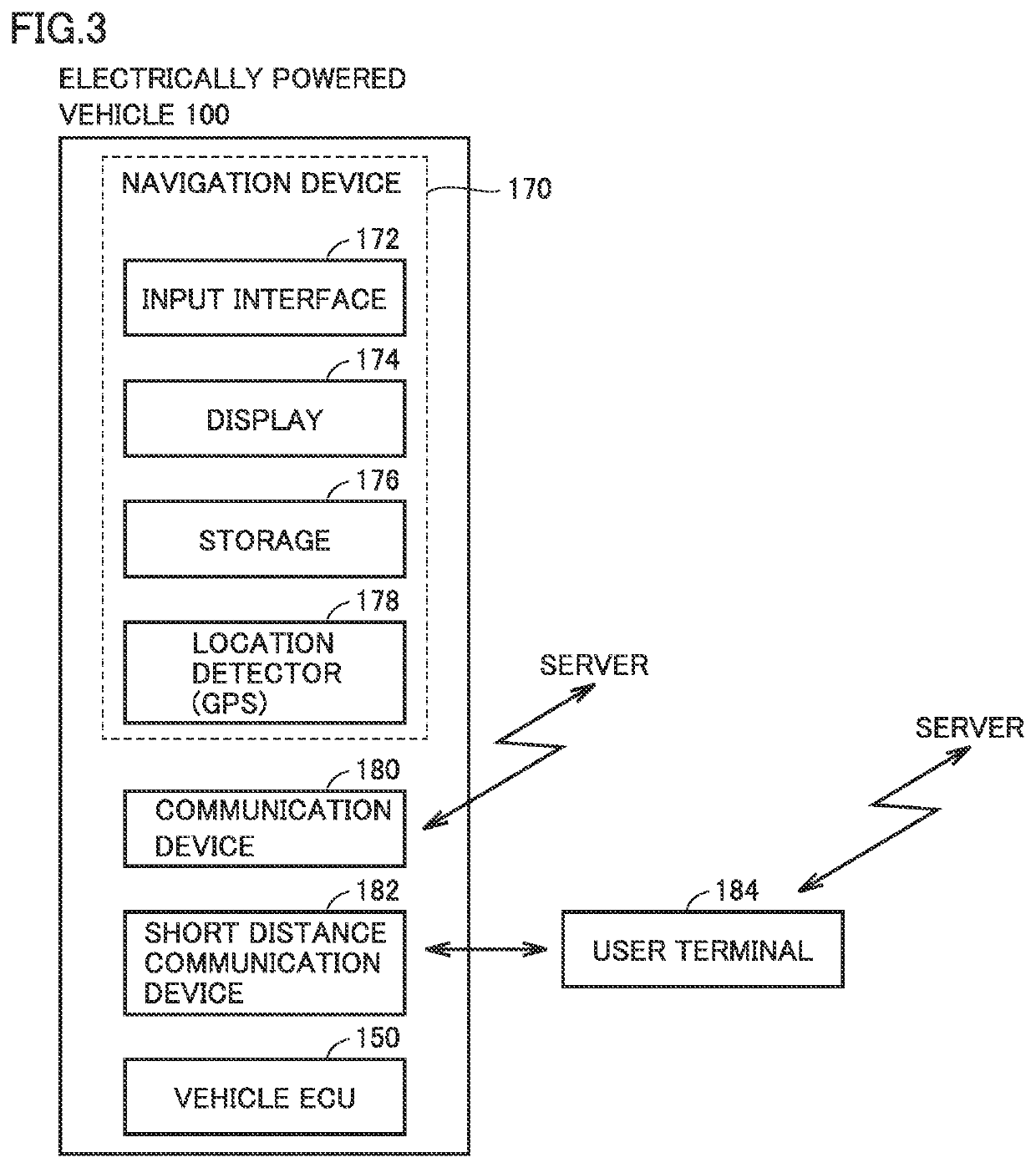
The patent describes a system where a server converts the amount of power used by a vehicle at a power installation into a value index, and provides this to the user of the vehicle. This allows for flexible operation based on the power value during use, and reduces power conversion loss compared to simply managing the power amount. As a result, the user can easily use the power stored in the vehicle at another time or location. The server also sets a higher value index when the power storage device is collected or replaced at a lower state of charge, encouraging the user to use the power before collecting or replacing it. This reduces the frequency of power storage device collection or replacement. The user can easily set any of the power installations as a destination using the navigation device after checking the value index and location information. Overall, the system enables efficient use of power and provides flexibility for the user to use the power stored in the vehicle at another time or location.

Problems solved by technology

Generally, when a vehicle supplies power (discharges) and receives power (charged) using a power installation, power conversion loss may occur in the vehicle or the power installation.
Thus, if a user of a vehicle that performed discharging to a power installation is allowed to perform charging at another time or another power installation for the same power amount as the amount of power discharged from that vehicle, loss corresponding to the power conversion loss may occur for a company that runs the power installations.

Method used


Image

  • Power management system, server and vehicle
  • Power management system, server and vehicle
  • Power management system, server and vehicle

Examples


modification 1

[0107]In the embodiment described above, server 300 may set, separately for each vehicle 100 and each power station 200, the value of the “added points” used for calculating the value points in the point process (step S20 of FIG. 6).

[0108]FIG. 9 is a sequence diagram showing an exemplary process performed between vehicles 100 and server 300 according to modification 1. In order to simplify the description, FIG. 9 shows an example where three vehicles 100 with IDs “001,”“002” and “003,” respectively, are communicating with server 300.

[0109]Server 300 requests each vehicle 100 to transmit location information of each vehicle (step S30). In response to the request from server 300, each vehicle 100 transmits the location information (GPS information) of its own vehicle to server 300 (step S40).

[0110]When server 300 receives the location information of each vehicle, server 300 performs an “added point setting process” of setting a value of added points for using each power station 200 by...

modification 2

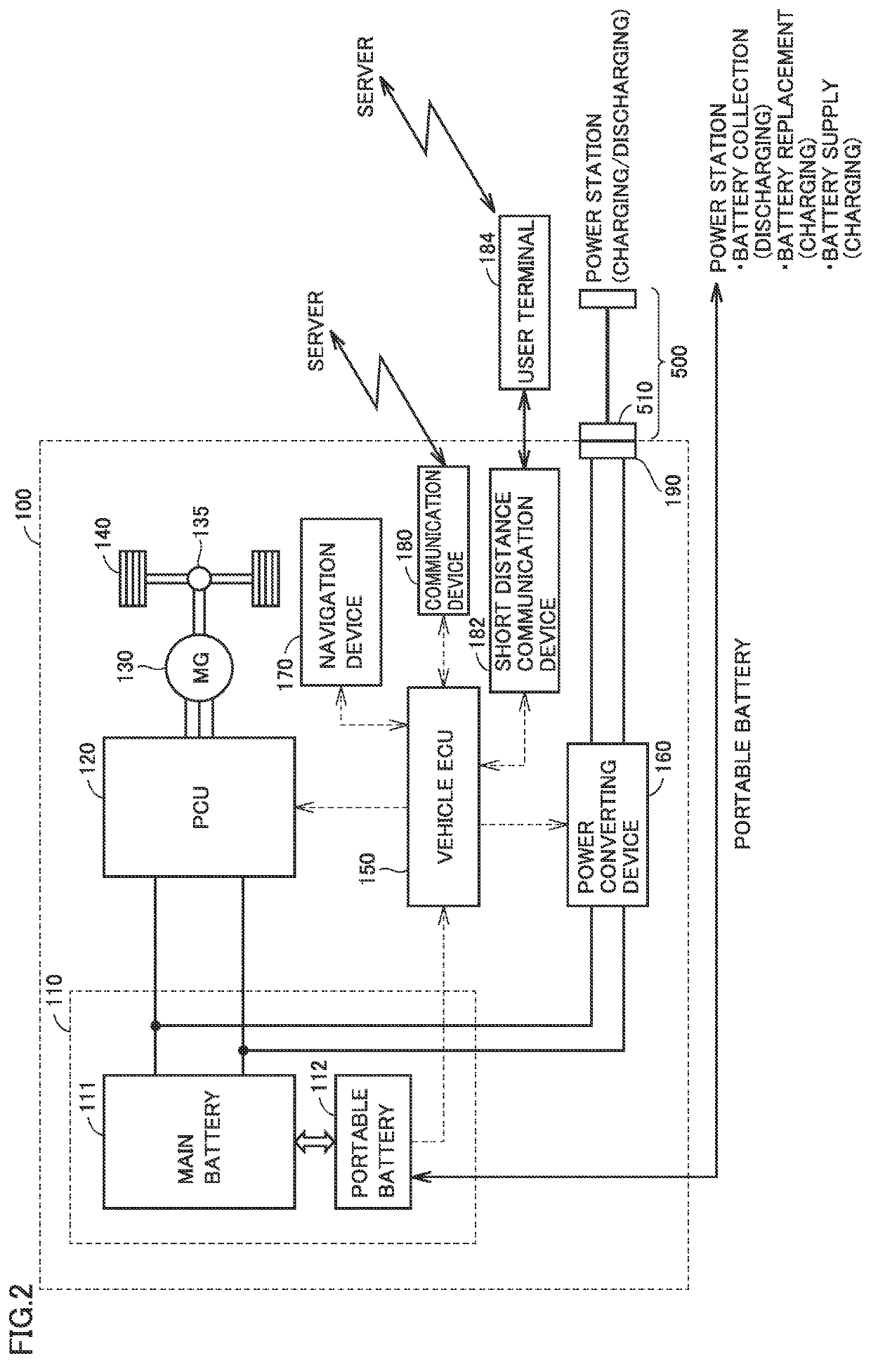
[0117]In the added point setting process (step S32 of FIG. 9) described above, server 300 may set the added points to a higher value when the state of charge of portable battery 112 collected at power station 200 by the battery replacement is lower.

[0118]FIG. 11 shows exemplary added points set in modification 2. In FIG. 11, the added points when the state of charge of portable battery 112 collected at each power station 200 by the battery replacement (pre-replacement SOC) is “low,”“middle” and “high” are set to “+500 points,”“0 point” and “−100 points,” respectively. With such setting, the user can be encouraged to use up as much power stored in portable battery 112 as possible before performing the battery replacement. The battery replacement frequency can thus be kept at low level.

[0119]Although not shown in FIG. 11, the value points (added points) may be set to a higher value when the state of charge of portable battery 112 collected at each power station 200 by the battery coll...

modification 3

[0120]In the added point setting process (step S32 of FIG. 9) described above, server 300 may set, separately for each power station 200, the added points for the battery collection, the added points for the battery replacement, and the added points for the battery supply. By setting a separate value point for each of the actions of battery collection, battery replacement and battery supply in this manner, value can be generated for physically transporting portable battery 112 between the power stations, thereby reducing the total power transport cost.

[0121]FIG. 12 shows exemplary added points set in modification 3. In the example shown in FIG. 12, at power station A, the added points for the battery collection are set to “+500 points,” and the added points are not provided to the other battery replacement and battery supply. At power station C, on the other hand, the added points for the battery supply are set to “+500 points,” and the added points are not provided to the other bat...


PUM


Abstract

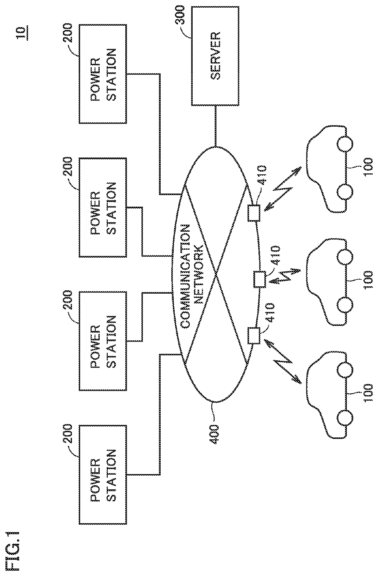
A power management system includes a plurality of power stations, a plurality of vehicles capable of exchanging power with any of the power stations, and a server configured to communicate with the plurality of vehicles and the plurality of power stations. When each power station receives power from the vehicle or supplies power to the vehicle, each power station associates a power amount received from the vehicle or a power amount supplied to the vehicle with a user ID of the vehicle, and transmits the power amount to the server. The server sets a value point based on the power amount received from the power station, and provides the value point to the user having the user ID associated with the power amount.

Description

[0001]This nonprovisional application is based on Japanese Patent Application No. 2017-206311 filed on Oct. 25, 2017 with the Japan Patent Office, the entire contents of which are hereby incorporated by reference.BACKGROUNDField[0002]The present disclosure relates to a system for managing electric power exchanged between a vehicle and a power station, a server, and a vehicle for use in the system.Description of the Background Art[0003]Japanese Patent Laying-Open No. 2017-73915 discloses an electrically powered vehicle capable of supplying electric power to the outside of the vehicle. When this electrically powered vehicle is present in a designated disaster area, the lower limit of a SOC (State of Charge) of a vehicle-mounted power storage device is lowered. This allows the electrically powered vehicle to supply more power to the outside of the vehicle in the disaster area.SUMMARY[0004]As electrically powered vehicles become more prevalent in the future, it is expected that there wi...

Claims


Application Information

Patent Timeline
Patent Type & Authority Patents(United States)
IPC IPC(8): B60L55/00B60L53/65B60L53/66B60L53/68B60L53/67
CPCB60L55/00B60L53/65B60L53/665B60L53/68B60L53/67B60L2240/72B60L53/00B60L53/80B60L53/60Y02T90/16Y02T90/167Y02T10/70Y02T90/14Y02T10/7072Y02T90/12Y04S30/12Y04S30/14Y04S10/126Y02E60/00
Inventor MIZUTANI, ATSUSHIKANEICHI, DAIKIKARUBE, HIROTAKAKONDO, JUNKOMURO, KENICHI
Owner TOYOTA JIDOSHA KK
Learn More