Torque fluctuation absorbing apparatus
a fluctuation absorbing apparatus and torque technology, applied in the direction of rotating vibration suppression, vibration suppression adjustment, spring/damper, etc., can solve the problems of reducing sliding torque, hysteresis, loss of load, etc., and achieve hysteresis torque, less frictional loss, and hysteresis torque.
- Summary
- Abstract
- Description
- Claims
- Application Information
AI Technical Summary
Benefits of technology
Problems solved by technology
Method used
Image
Examples
first exemplary embodiment
[0051]The torque fluctuation absorbing apparatus according to a First Exemplary Embodiment of the present invention will be described below with reference to the accompanying drawings.
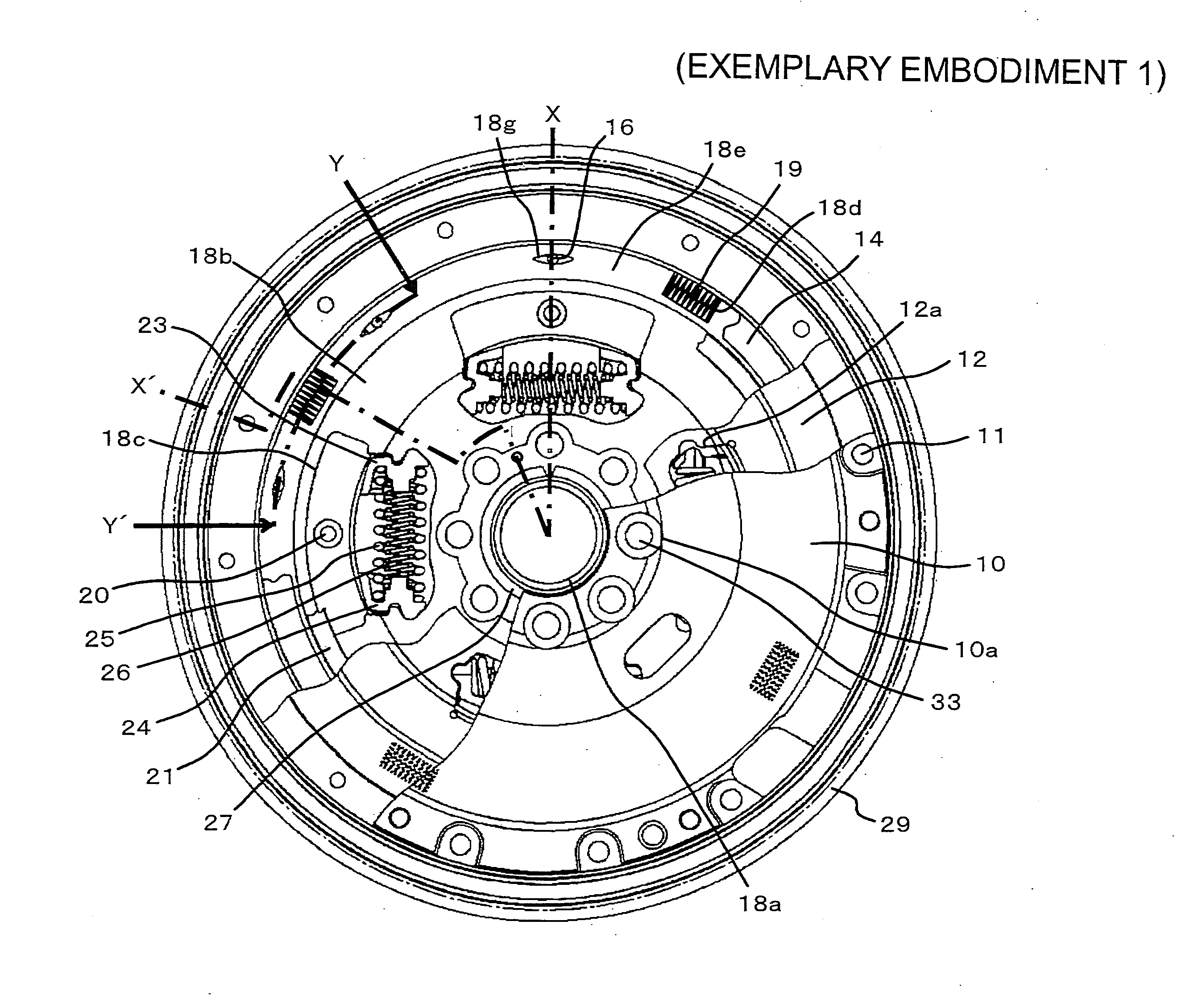
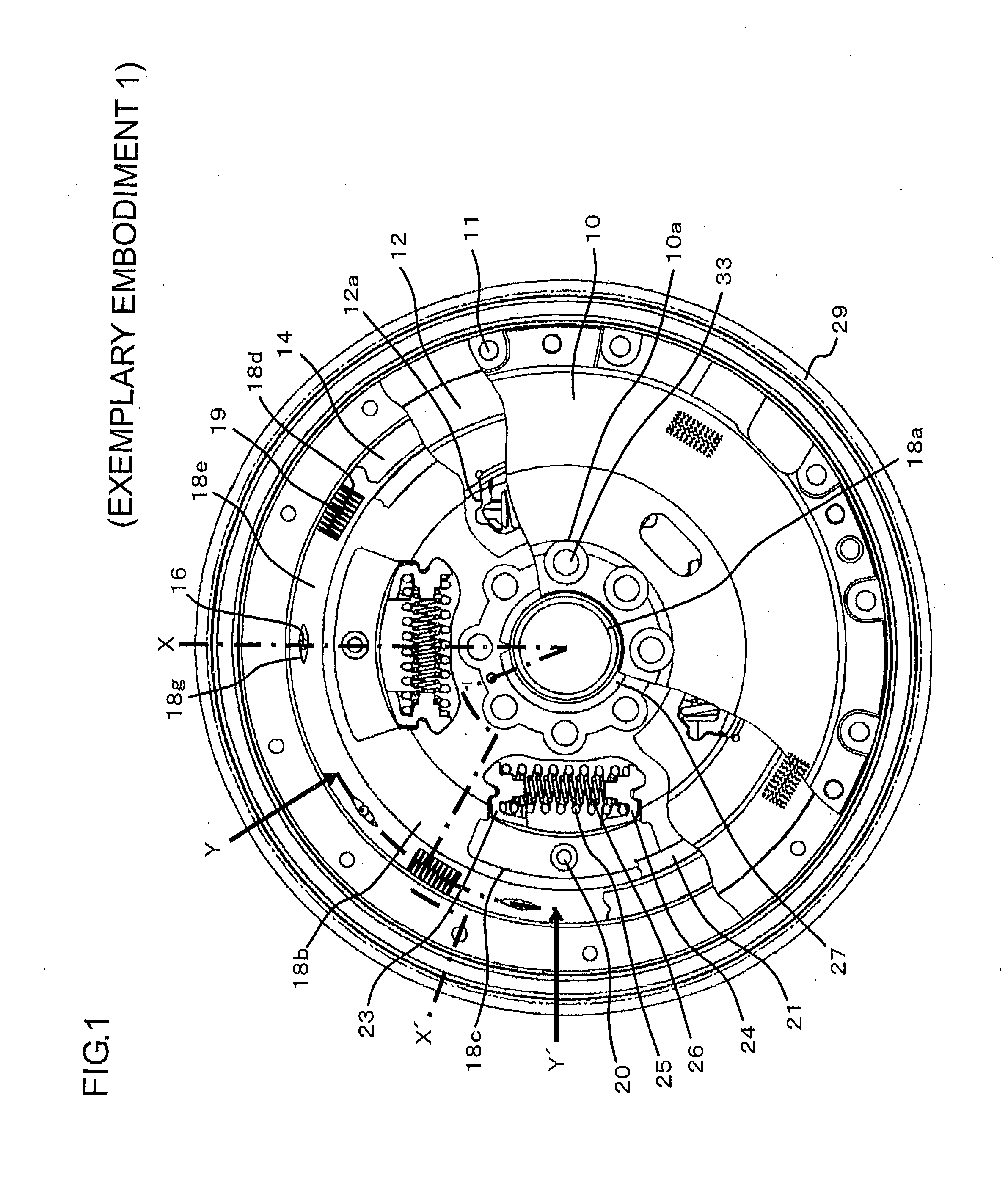
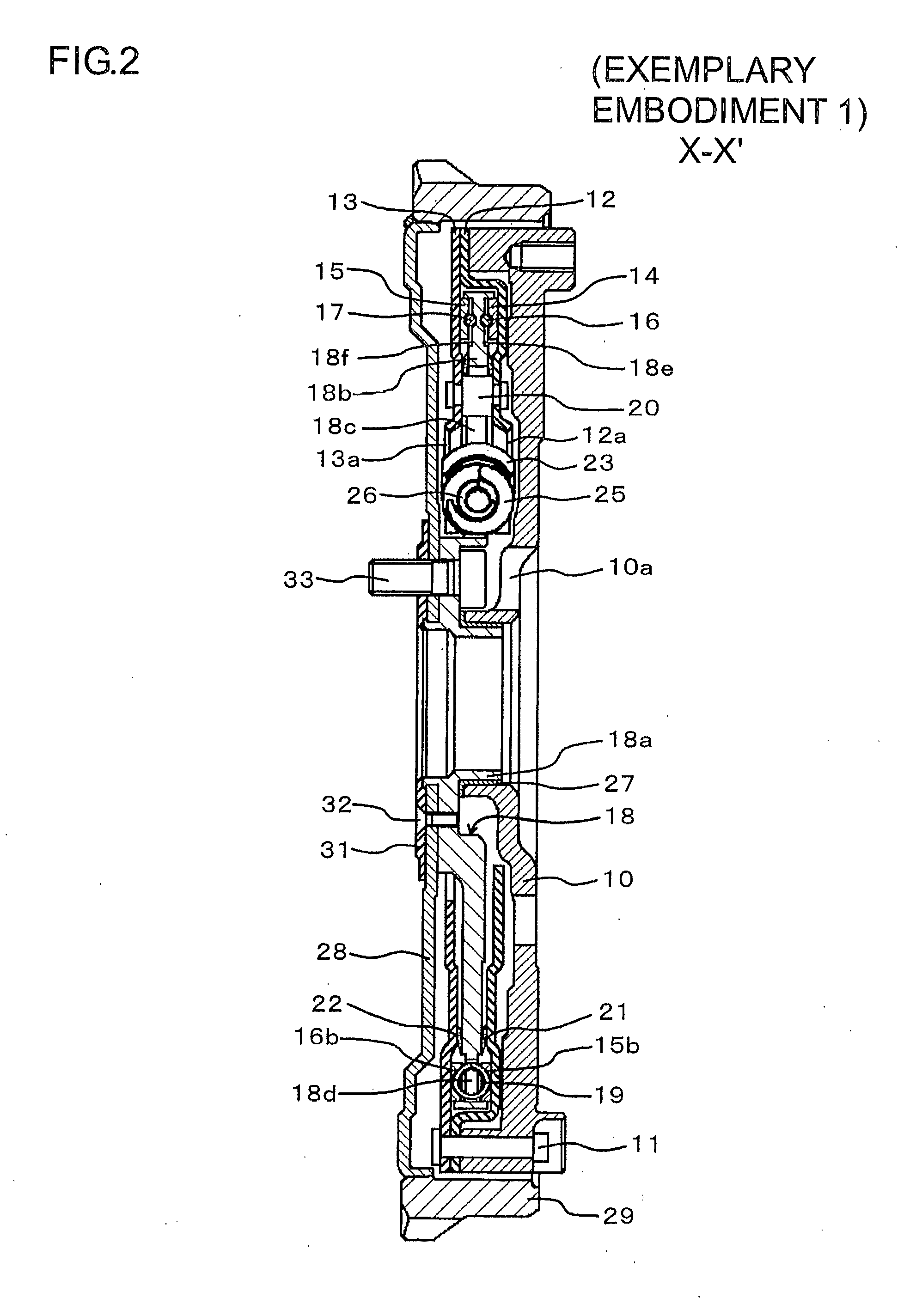
[0052]FIG. 1 is a partially cut-away plan view schematically showing the formulation of a torque fluctuation absorbing apparatus according to the First Exemplary Embodiment of the present invention. FIG. 2 is a sectional view taken along line X-X′ in FIG. 1 schematically showing the formulation of the torque fluctuation absorbing apparatus according to First Exemplary Embodiment of the present invention. FIG. 3 is a sectional view taken along line Y-Y′ in FIG. 1 schematically showing the formulation of the torque fluctuation absorbing apparatus according to First Exemplary Embodiment of the present invention. In FIG. 3, a flywheel 10 and a plate member 28 are omitted.
[0053]The torque fluctuation absorbing apparatus is mounted on an output shaft (not shown) of an engine (not shown), and absorbs (suppres...
second exemplary embodiment
[0083]Now the torque fluctuation absorbing apparatus according to Second Exemplary Embodiment of the present invention will be described by making reference to the accompanying drawings. FIG. 4 is a sectional view schematically showing a part of the formulation of the torque fluctuation absorbing apparatus according to Second Exemplary Embodiment of the present invention. FIG. 4 corresponds to a part of the section along line Y-Y′ in FIG. 1 (vicinity of the rolling element 16).
[0084]In First Exemplary Embodiment, surfaces of the recesses (14a, 15a of FIG. 3) of the thrust plates (14, 15 of FIG. 3) and the recesses (18g, 18h of FIG. 3) of the flange portion (18b of FIG. 3) have warped shapes, although in Second Exemplary Embodiment, surfaces of the recesses 14c, 15c of the thrust plates 14, 15 and the recesses 18i, 18j of the flange portion 18b have flat tapered (sloped) shapes (or flat tapers). In other respect, the formulation is similar to that of First Exemplary Embodiment. Accor...
third exemplary embodiment
[0085]Now the torque fluctuation absorbing apparatus according to Third Exemplary Embodiment of the present invention will be described by making reference to the accompanying drawings. FIG. 5 is a sectional view schematically showing a part of the formulation of the torque fluctuation absorbing apparatus according to Third Exemplary Embodiment of the present invention. FIG. 5 corresponds to a part of the section along line Y-Y′ in FIG. 1 (vicinity of the rolling element 16).
[0086]In First Exemplary Embodiment, surfaces of the recesses (14a, 15a of FIG. 3) of the thrust plates (14, 15 of FIG. 3) and the recesses (18g, 18h of FIG. 3) of the flange portion (18b of FIG. 3) have symmetrical shapes with the same shapes on both sides in the circumferential direction, with respect to a radial line running through the center (deepest portion) of the recesses (14a, 15a, 18g, 18h of FIG. 3) in the radial direction, although in Third Exemplary Embodiment, surfaces of the recesses 14d, 15d of t...
PUM
 Abstract
Description
Claims
Application Information
 - R&D
- Intellectual Property
- Life Sciences
- Materials
- Tech Scout
- Unparalleled Data Quality
- Higher Quality Content
- 60% Fewer Hallucinations
Browse by: Latest US Patents, China's latest patents, Technical Efficacy Thesaurus, Application Domain, Technology Topic, Popular Technical Reports.
© 2025 PatSnap. All rights reserved.Legal|Privacy policy|Modern Slavery Act Transparency Statement|Sitemap|About US| Contact US: help@patsnap.com


