
Protecting agent-supplying device, process cartridge, image forming apparatus

a technology of protection agent and supply device, which is applied in the direction of optics, instruments, electrography/magnetography, etc., can solve the problems of affecting the lubricity of former lubricant, affecting the lubricity of the former lubricant, and abrading and scratching the image bearing member

Active Publication Date: 2015-03-31
RICOH KK
View PDF48 Cites 0 Cited by
  • Summary
  • Abstract
  • Description
  • Claims
  • Application Information

AI Technical Summary

Benefits of technology

The present invention relates to a protecting agent-supplying device, an image forming apparatus, and an image forming method using the device and method. The device includes a rotation member and an image bearing member-protecting agent that is in solid form. The image bearing member-protecting agent is scraped off by the rotation of the rotation member and supplied to the image bearing member for protection. The device is designed to prevent non-uniform consumption and elongate the life of the image bearing member-protecting agent. The image bearing member-protecting agent can be consistently supplied for a long period of time and can clean the image bearing member effectively, preventing deterioration. The image forming method using the protecting agent can also prevent staining of the charging unit and other members. This method contributes to longer service lives for the image bearing member and other members, reduces running costs, and promotes waste reduction.

Problems solved by technology

For example, as has been known, the stress caused by the friction in the cleaning step abrades and scratches the image bearing member, and also abrades the cleaning member in the cleaning step.
That is, it has been known that the former lubricant promptly loses its lubricity due to discharge performed near an image bearing member in the charging step.
As a result, the lubricities of the cleaning blade and the image bearing member are impaired, and the toner particles run through between the cleaning blade and the image bearing member, causing image failure.
Moreover, since with use of the former lubricant the toner running through frequently occurs, and the cleaning blade is abraded, and the service life of an image forming apparatus may be shortened.
Then, when the brush deteriorates over time, the consumption of the lubricant decreases, and the image bearing member is not sufficiently protected, causing filming.
In such case, the pressure of the brush is not uniformly applied to the solid lubricant in the longitudinal direction of the solid lubricant, and the lubricant is not uniformly scraped off in the longitudinal direction thereof.
Thus, a nonuniformly consumed part is consumed faster than the set service life, causing shortening of the service life of an entire image forming apparatus.
However, since the above-described technique uses the former lubricant, the former lubricant promptly loses its lubricity due to discharge performed near an image bearing member in the charging step.
As a result, the lubricities of the cleaning blade and the image bearing member are impaired, and the toner particles run through a gap between the cleaning blade and the image bearing member, causing image failure.
Moreover, since with use of the former lubricant the toner running through frequently occurs, a cleaning blade is abraded, and the lubricant is nonuniformly consumed, causing shortening of the service life of an image forming apparatus.
Moreover, the technique is not positioned as a countermeasure to the nonuniform consumption of the lubricant.

Method used


Image

  • Protecting agent-supplying device, process cartridge, image forming apparatus
  • Protecting agent-supplying device, process cartridge, image forming apparatus
  • Protecting agent-supplying device, process cartridge, image forming apparatus

Examples


example 1

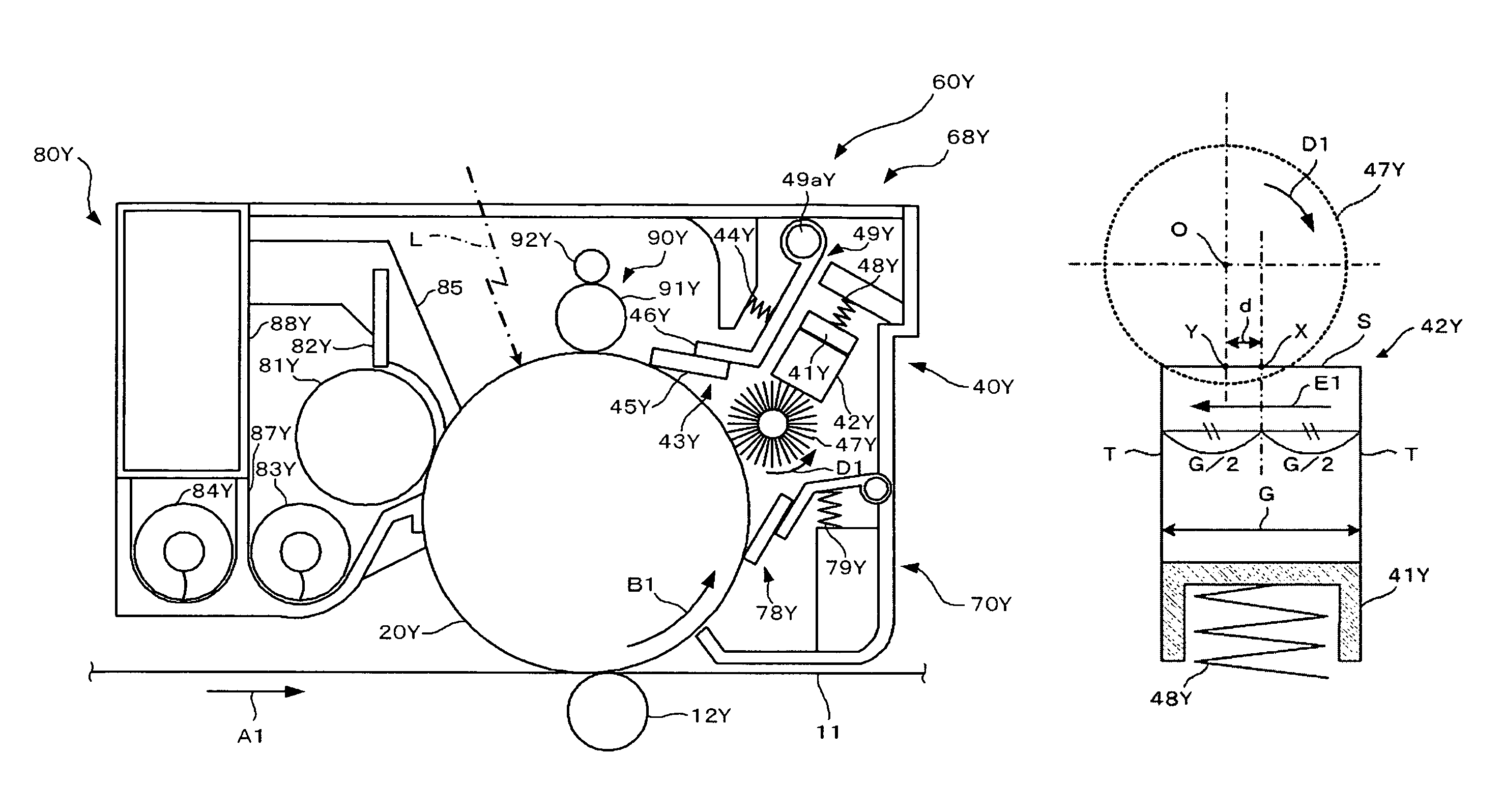
[0315]A protecting agent used was formed through compression molding of a mixture of a fatty acid metal salt and an inorganic lubricant in the ratio by mass of 8:2. The fatty acid metal salt was zinc stearate (product of NOF CORPORATION), and the inorganic lubricant was boron nitride (product of Momentive Performance Materials Inc.). As shown in FIG. 7A, the position X was located upstream in the direction E1 from the position Y, and the distance d was 1 mm.

example 2

[0316]A protecting agent used was formed through compression molding of a mixture of a fatty acid metal salt and an inorganic lubricant in the ratio by mass of 8:2. The fatty acid metal salt was zinc stearate (product of NOF CORPORATION), and the inorganic lubricant was boron nitride (product of Momentive Performance Materials Inc.). As shown in FIG. 7A, the position X was located upstream in the direction E1 from the position Y, and the distance d was 2 mm.

example 3

[0317]A protecting agent used was formed through compression molding of a mixture of a fatty acid metal salt and an inorganic lubricant in the ratio by mass of 8:2. The fatty acid metal salt was zinc stearate (product of NOF CORPORATION), and the inorganic lubricant was boron nitride (product of Momentive Performance Materials Inc.). As shown in FIG. 7A, the position X was located upstream in the direction E1 from the position Y, and the distance d was 4 mm.


PUM


Abstract

A protecting agent-supplying device including: a rotation member configured to rotate in a certain direction; an image bearing member-protecting agent containing a fatty acid metal salt and an inorganic lubricant, and being in the form of a solid, wherein the agent is scraped off by the rotation of the rotation member, supplied to an image bearing member for protection thereof, and disposed to have a surface facing the rotation member, which surface has a width G in a direction along the certain direction, and wherein the position X (a center of the width G) is located upstream in the direction along the certain direction from the position Y (a line of intersection between the surface facing and a line extended from the rotational center of the rotation member perpendicular to the surface facing), and a distance d between these positions satisfies a formula 0<d≦G / 2.

Description

BACKGROUND OF THE INVENTION[0001]1. Field of the Invention[0002]The present invention relates to a protecting agent-supplying device which supplies an image bearing member-protecting agent to an image bearing member provided in image forming apparatuses such as copiers, facsimiles and printers, a process cartridge including the protecting agent-supplying device, an image forming apparatus including the protecting agent-supplying device.[0003]2. Description of the Related Art[0004]In image forming apparatuses (e.g., copiers, facsimiles and printers) having an image bearing member (e.g., a photoconductor made of, for example, a photoconductive material, or the like), the image bearing member is rotated and subjected sequentially to a charging step, an exposing step, a developing step, a transfer step and a fixing step, etc. for image formation.[0005]In the charging step, a surface of the image bearing member is charged with a charging member such as a charging roller. In the exposing ...

Claims


Application Information

Patent Timeline
Patent Type & Authority Patents(United States)
IPC IPC(8): G03G21/00
CPCG03G21/0094
Inventor HASEGAWA, KUNIONAKAI, HIROSHITANAKA, SHINYAYAMAMOTO, KOHSUKEURAYAMA, TAICHI
Owner RICOH KK
Learn More