Eureka AIR delivers breakthrough ideas for toughest innovation challenges, trusted by R&D personnel around the world.

Cable lifting apparatus

a cable and cable technology, applied in the direction of hoisting equipment, winding mechanisms, etc., can solve the problems of increasing reducing the service life, etc., and achieve the effect of reducing the wear and tear of the cable, increasing the service life, and reducing the wear of the cabl

Inactive Publication Date: 2010-08-19
ELEVADORES GOIAN
View PDF8 Cites 2 Cited by
  • Summary
  • Abstract
  • Description
  • Claims
  • Application Information

AI Technical Summary

Benefits of technology

[0007]The third mentioned document describes a system in which the radial pressure exerted on the cable is a function that depends on the load to be lifted, whereby reducing the wear of the cable and increasing its service life in comparison to the solutions of the first two documents.
[0008]The present invention is intended for a cable lifting apparatus in which the pressure exerted on the cable depends, as in the mentioned case of the last document, on the load to be lifted, but with the particularity that it is affected by two different factors. The first factor is provided directly by the load to be lifted, whereas the second factor derives from the tangential reaction of the drive pinion mounted at the output of the reducer, meshed with a crown gear integral with the traction sheave. By means of this dual effect, an implementation can be carried out in which the angle of the groove the traction sheave is provided with can be of larger dimensions than that in sheaves of the traditional embodiments, which further reduces the wear of the cable and also elongates the service life of said cable.
[0009]Providing a lifting apparatus in which multiple cables are implemented, thereby considerably increasing the safety of lifting people and loads, is also an object of the present invention.
[0010]According to the invention, the pinching effect of the rollers on the suspension cable is achieved as a result of providing a rotating box containing the gears and the drive sheave. Since the output shaft of the reducer coincides with the rotating shaft of the box, the tangential reaction occurring in the periphery of the pinion associated with the output of the reducer, due to the torque applied by the reducer (which always acts in the same direction, either as a motor or as a brake), is vectorially added to the reaction due to the suspension cable, which allows modulating the force exerted by the pressure rollers, precisely adjusting it to its optimal value both from the point of view of the absence of sliding and from the point of view of greater durability of the cable.

Problems solved by technology

This solution has the drawback that the cable experiences constant radial stresses equivalent to those of the maximum load to be lifted or withstood, whereby increasing the wear of said cable and reducing its service life.

Method used


Image

  • Cable lifting apparatus
  • Cable lifting apparatus
  • Cable lifting apparatus

Examples


Embodiment Construction

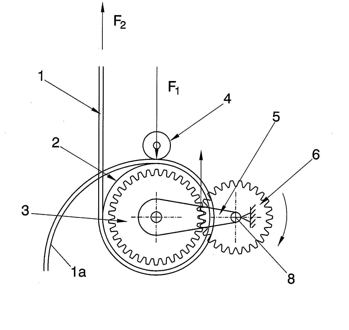
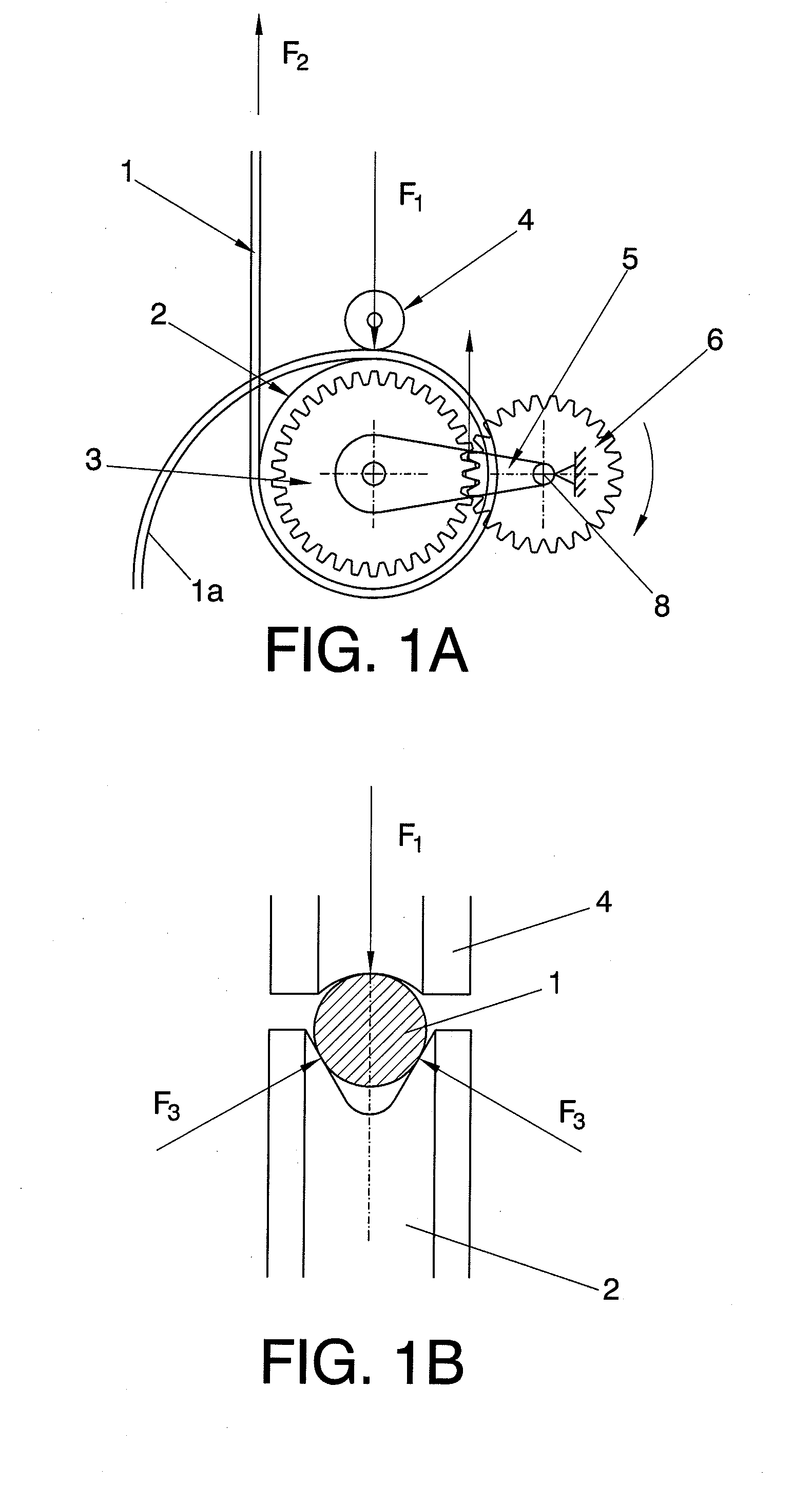
[0016]As mentioned above, the detailed description of the preferred embodiments of the invention will be given below with the aid of the attached drawings, through which the same reference numbers will be used to designate identical or similar parts. Therefore, first of all with respect to FIG. 1 of the drawings, depictions (a) and (b), illustrative diagrams of the operating principles of the apparatus of the invention can be seen. Depiction (a) of the mentioned figure shows an extended suspension cable 1 such that it passes through the peripheral groove made in a drive sheave 2 incorporating a gear wheel 3 integral with a side surface thereof, concentric with respect to the rotating shaft of said sheave 2. A pinion 6 is meshed with the mentioned gear wheel 3, being maintained in its operative position by means of a connecting rod 5 extending between the rotating shaft 8 common for said sheave 2 and associated gear wheel 3, and the rotating shaft of the pinion 6, keeping the relativ...


PUM


Abstract

The invention relates to a cable lifting apparatus for lifting people or loads, including a traction sheave provided with a peripheral groove housing a suspension cable against which rollers apply a pressure in order for the traction sheave to perform the pulling function thereof. The apparatus is designed such that the radial load on the cable is a function of the load to be lifted and of the torque applied by a pinion mounted at the output of the reduction power unit and meshed with a gear wheel integrally connected to, and rotatably concentric with, the traction sheave. The described apparatus allows using a variable number of cables, either by means of the use of a modified sheave provided peripherally with as many grooves as there are cables and having an independent group of pressure rollers for each cable or through the formation of grooves between portions separated by notches made in radial planes between successive portions and having a single group of pressure rollers for all of the cables.

Description

OBJECT OF THE INVENTION[0001]The present invention relates to a cable lifting apparatus, providing essential novel features and considerable advantages with respect to the systems known and used for the same purposes in the current state of the art.[0002]More particularly, the invention relates to a cable lifting apparatus comprising one or several drive sheaves and one or several continuous cables (as many as there are sheaves), in which the load section of each cable passes through the groove of sheave existing around the periphery of each respective one of the drive sheaves to which it is associated, pressed by several rollers mounted according to the peripheral direction of each sheave, whereas the loose section of each cable exits through the respective groove of the sheave behind the pressure rollers.[0003]The field of application of the invention is obviously comprised in the industrial sector dedicated to the design, manufacture and assembly of lifting apparatuses, generally...

Claims


Application Information

Patent Timeline
Patent Type & Authority Applications(United States)
IPC IPC(8): B66D1/74B66D1/50
CPCB66D1/7489B66D1/7415
Inventor ASENSIO BAZTERRA, JUAN JULIANDEL POZO POLIDORO, ENRIQUE
Owner ELEVADORES GOIAN
Why Eureka
Eureka Blog
Learn More