Display device having grooves disposed on a surface of retaining wall

a technology of retaining wall and display device, which is applied in the field of display devices, can solve problems such as reducing product yield, and achieve the effect of improving the reliability of the oled panel package and prolonging the service life of the oled devi

Active Publication Date: 2022-01-11
WUHAN CHINA STAR OPTOELECTRONICS SEMICON DISPLAY TECH CO LTD
View PDF9 Cites 1 Cited by
  • Summary
  • Abstract
  • Description
  • Claims
  • Application Information

AI Technical Summary

Benefits of technology

[0004]The technical problem mainly solved by the present application is how to improve the reliability of the OLED panel package and thereby improve the service life of the OLED device.
[0046]Beneficial effects of the present application are that: by providing a plurality of grooves on the retaining wall, a contact area between the encapsulating film and the retaining wall is increased, and the reliability of the OLED panel package is improved, thereby elongating the service life of the OLED device.

Problems solved by technology

However, an OLED display panel is prone to a delamination problem of an encapsulation layer and its underlying layers during a bending process, resulting in failure of the OLED display panel, thereby reducing product yield.

Method used


Image

  • Display device having grooves disposed on a surface of retaining wall
  • Display device having grooves disposed on a surface of retaining wall
  • Display device having grooves disposed on a surface of retaining wall

Examples


first embodiment

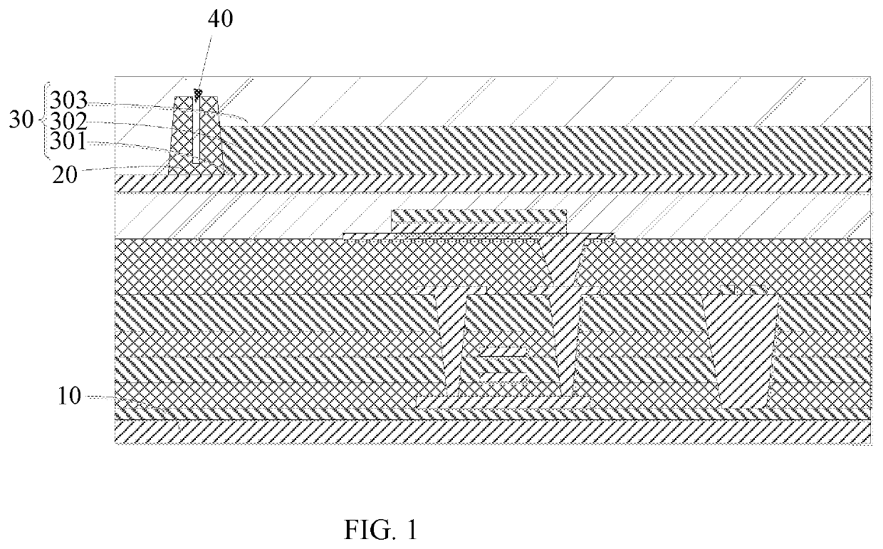
[0058]Please refer to FIG. 1. FIG. 1 is a schematic structural diagram of a display panel provided by the present application.

[0059]The present application provides a display panel 1 including a substrate 10, a retaining wall 20, and an encapsulating film 30. The retaining wall 20 is disposed on the substrate 10, and the encapsulating film 30 is disposed on the retaining wall 20 and covers the substrate 10. A plurality of grooves 40 are further disposed on a surface of the retaining wall 20 facing the encapsulating film 20, and the encapsulating film 20 extends into the plurality of grooves 40.

[0060]For example, the substrate 10 may be a flexible substrate on which a planarization layer, a pixel defining layer, an anode, a light-emitting layer, and a cathode may be formed. The retaining wall 20 is disposed at an edge region of the pixel defining layer 20 for preventing water and oxygen in the outside from invading from a side of the display panel 1, resulting in failure of the light...

third embodiment

[0068]In some embodiments, please refer to FIG. 4. FIG. 4 is a schematic plan view of the display panel provided by a third embodiment shown in FIG. 1. The present application also provides a display panel 1. A difference between the display panel 1 of FIG. 3 and the display panel 1 of FIG. 2 is that the retaining wall 20 includes a first sub-retaining wall 201 and a second sub-retaining wall 202 that are spaced apart from each other, and the grooves 40 includes first sub-grooves 401 and second sub-grooves 402. The plurality of first sub-grooves 401 are spaced apart from each other and disposed on the first sub-retaining wall 301, and the plurality of second sub-grooves 402 are spaced apart from each other and disposed on the second sub-retaining wall 302.

[0069]For example, in a direction from the edge region to the central region of the substrate 10, the first sub-retaining wall 201 and the second sub-retaining wall 202 are spaced apart and disposed on the first end 102, and the fi...

fourth embodiment

[0075]In some embodiments, please refer to FIG. 5. FIG. 5 is a schematic plan view of the display panel provided by a fourth embodiment shown in FIG. 1. The present application also provides a display panel 1. A difference between the display panel 1 of FIG. 4 and the display panel 1 of FIG. 2 is that the plurality of first sub-grooves 401 and the plurality of second sub-grooves 402 are staggered alternately from each other; and each of the second sub-grooves 402 is correspondingly disposed at an interval between its adjacent ones of the first sub-grooves 401.

[0076]For example, the first sub-grooves 401 are spaced apart from each other and disposed on the first sub-retaining wall 201 by a number of ten, and there is an interval between adjacent ones of the first sub-grooves 401, that is, there are nine intervals. Each of the second sub-grooves 402 is disposed at an interval of the adjacent ones of the first sub-grooves 401, that is, the second sub-grooves 402 are respectively dispos...


PUM

PropertyMeasurementUnit
heightaaaaaaaaaa
depthaaaaaaaaaa
distanceaaaaaaaaaa

Abstract

The present application provides a display panel and a display device, wherein the display panel includes: a substrate; a retaining wall disposed on the substrate; and an encapsulating film disposed on the retaining wall and covering the substrate, wherein a plurality of grooves are further disposed on a surface of the retaining wall facing the encapsulating film, and the encapsulating film extends into the grooves.

Description

BACKGROUND OF INVENTIONField of Invention[0001]The present application relates to a field of display technologies, and in particular, to a display panel and a display device.Description of Prior Art[0002]As a current-type light-emitting device, an organic light-emitting diode (OLED) has received wide attention because of its self-illumination, rich colors, fast response time, wide viewing angles, light weight, and applications on flexible display.[0003]However, an OLED display panel is prone to a delamination problem of an encapsulation layer and its underlying layers during a bending process, resulting in failure of the OLED display panel, thereby reducing product yield.SUMMARY OF INVENTION[0004]The technical problem mainly solved by the present application is how to improve the reliability of the OLED panel package and thereby improve the service life of the OLED device.[0005]In a first aspect, the present application provides a display panel, including:[0006]a substrate;[0007]a r...

Claims


Application Information

Patent Timeline
Patent Type & Authority Patents(United States)
IPC IPC(8): H01L27/32H01L51/52
CPCH01L51/5253H01L27/3244H10K59/12H10K50/844H10K2102/311
Inventor WU, SHAOJING
Owner WUHAN CHINA STAR OPTOELECTRONICS SEMICON DISPLAY TECH CO LTD
Why Eureka
Try Eureka