Eureka AIR delivers breakthrough ideas for toughest innovation challenges, trusted by R&D personnel around the world.

Suppressing method of wear in friction system between two objects

a friction system and wear-resistance technology, applied in the direction of manual lubrication, machines/engines, distribution equipment, etc., can solve the problems of damage to the friction surface, wear cannot be completely prevented, and the solid body generated in the lubricating oil is increased, so as to reduce the trouble in the lubricating oil system, prolong the overhaul period, and suppress the friction surface wear

Inactive Publication Date: 2010-10-26
SUMIMOTO SCI INST CO LTD
View PDF18 Cites 1 Cited by
  • Summary
  • Abstract
  • Description
  • Claims
  • Application Information

AI Technical Summary

Benefits of technology

[0007]In other words, an object of the present invention is to provide a method of suppressing a wear in a friction system between two objects which can significantly reduce a trouble in a lubricant system by indicating an optimum lubricating oil nature value and applying a lubricating oil regulated to the nature value to an internal combustion engine having various sizes and rotation sizes so that the lubricating oil for the engine keeps the nature value to an optimum level, and can suppress a wear of a friction surface in a slidable portion between a cylinder and a piston or between a bore and a shaft so that it is possible to make an overhaul period longer and extend a service life of the engine to the maximum.
[0008]A means which the present invention employs for solving the problem mentioned above is characterized in that an insoluble content is regulated so as to be within a range of a specific percentage content with respect to a lubricating oil so as to be contained, and is maintained, in a friction system in which the lubricating oil is interposed between two objects for the purpose of suppressing a wear due to an abrasion of a surface in a contact periodical relative motion between the two objects.
[0009]A corresponding value between the maximum rotation speed and the percentage content is structured such that in the case that a continuous monotone decreasing curve passing through a point (25 rpm, 0.8 mass %), a point (100 rpm, 0.5 mass %), a point (750 rpm, 0.2 mass %), a point (1200 rpm, 0.1 mass %), a point (3000 rpm, 0.05 mass %), and a point (8000 rpm, 0.025 mass %) can use a percentage content p of the insoluble content and can be expressed as a function of the maximum rotation speed n, that is, p(n) in which the points on a graph are expressed by (n, p), the graph adopting the maximum rotation speed n as a horizontal axis and the percentage content as a vertical axis, a percentage content P of the insoluble content with respect to the lubricating oil including an effective error range is given by a formula P(n)=p(n)±0.05 mass %, is regulated and maintained such as to contain the insoluble content with respect to the lubricating oil within the value range, and suppresses the wear due to the friction between the two objects.
[0012]Further, the means for regulating and maintaining the percentage content of the insoluble content with respect to the lubricating oil regulates and maintains the lubricating oil by using a precise filtering means. In this case, the precise filtering means in the present invention corresponds to a filtering means which has a filter element capable of precisely filtering the insoluble content of a combustion product, an incomplete combustion product or the like, and can regulate the percentage content of the insoluble content with respect to the lubricating oil within a target range, and is particularly structured such as to include a filter element formed by laminating a lot of thin sheets, and passes the lubricating oil through a paper laminated gap so as to makes an impurity constituted by the combustion product, the incomplete combustion product or the like contained in the lubricating oil to be attached to a paper fiber on the basis of a molecular Brownian motion and be removed. It is preferable that the precise filtering means can effectively remove the impurity having a size equal to or more than 1 μm, however, is not limited as far as the precise filtering means can achieve the object mentioned above.
[0014]In the friction surface to which the present invention is applied, and which is structured such as to always regulate and keep the percentage content of the insoluble content to a predetermined value in correspondence to the maximum rotation speed of the slide of the friction system, it is possible to suppress the wear of the friction surface to the minimum limit. As a result, it is possible to continuously keep the friction surface in an optimum state over a long period.
[0016]Further, it is possible to significantly reduce a trouble in the lubricating oil system such as a trouble that almost no combustion residual material is present in an exhaust valve or a turbine nozzle, or the like, and it is possible to make an overhaul period longer by significantly reducing the wear of the slidable portion such as the cylinder, the piston, the bore, the shaft or the like. As a result, it is possible to widely elongate a service life of the engine, and it is possible to reduce damage resulting from failures and during service and maintenance.

Problems solved by technology

However, the wear can not be completely prevented by interposing the lubricating oil in the friction surface, but can be only suppressed.
Among them, a solid body generated in the lubricating oil is increased with age at a time of being used and causes to damage the friction surface.
However, the inventors have found that the conventional systems mentioned above do not suppress a deterioration of the internal combustion engine due to the wear on the friction surface between the cylinder and the piston to the minimum, rather they damage the surfaces of the cylinder and the piston corresponding to guts of the engine by using the lubricating oil at an impurity percentage content set as the allowable limit exceeding by far the optimum value of the nature of the lubricating oil, so that a performance of the engine is lowered, and a service life is significantly shortened.

Method used


Image

  • Suppressing method of wear in friction system between two objects
  • Suppressing method of wear in friction system between two objects
  • Suppressing method of wear in friction system between two objects

Examples


embodiment 1

[0037]Next, a description will be given of one example to which the present invention is applied, and results of actual measurement thereof with reference to FIGS. 4 to 6, thereby viewing an effectiveness of the present invention. As shown in FIG. 4, the structure of the present embodiment is made such that a diesel engine at 750 rpm to the maximum, and a precise filtering means communicated therewith and filtering the lubricating oil 3 while circulating are provided, and the lubricating oil 3 is interposed in the friction surface 2 between the cylinder and the piston within the diesel engine, thereby suppressing the wear of the friction surface 3.

[0038]For example, as is apparent from a graph showing a state of a change with age of the percentage content of the pentane insoluble content in the diesel engine which is not provided with the precise filtering means, and the diesel engine in which the precise filtering means is placed, in a state of 750 rpm in FIG. 5, the percentage con...

embodiment 2

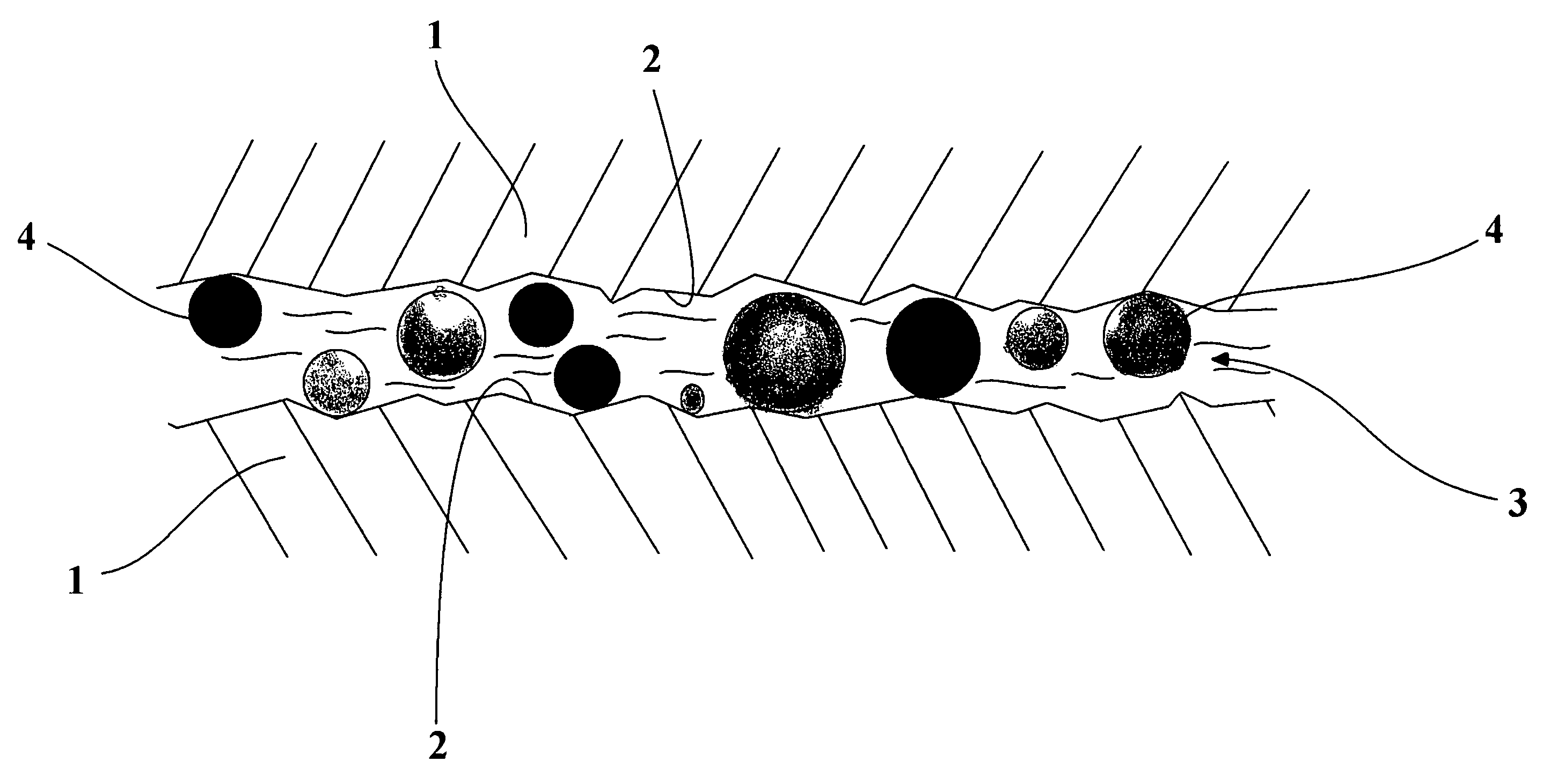
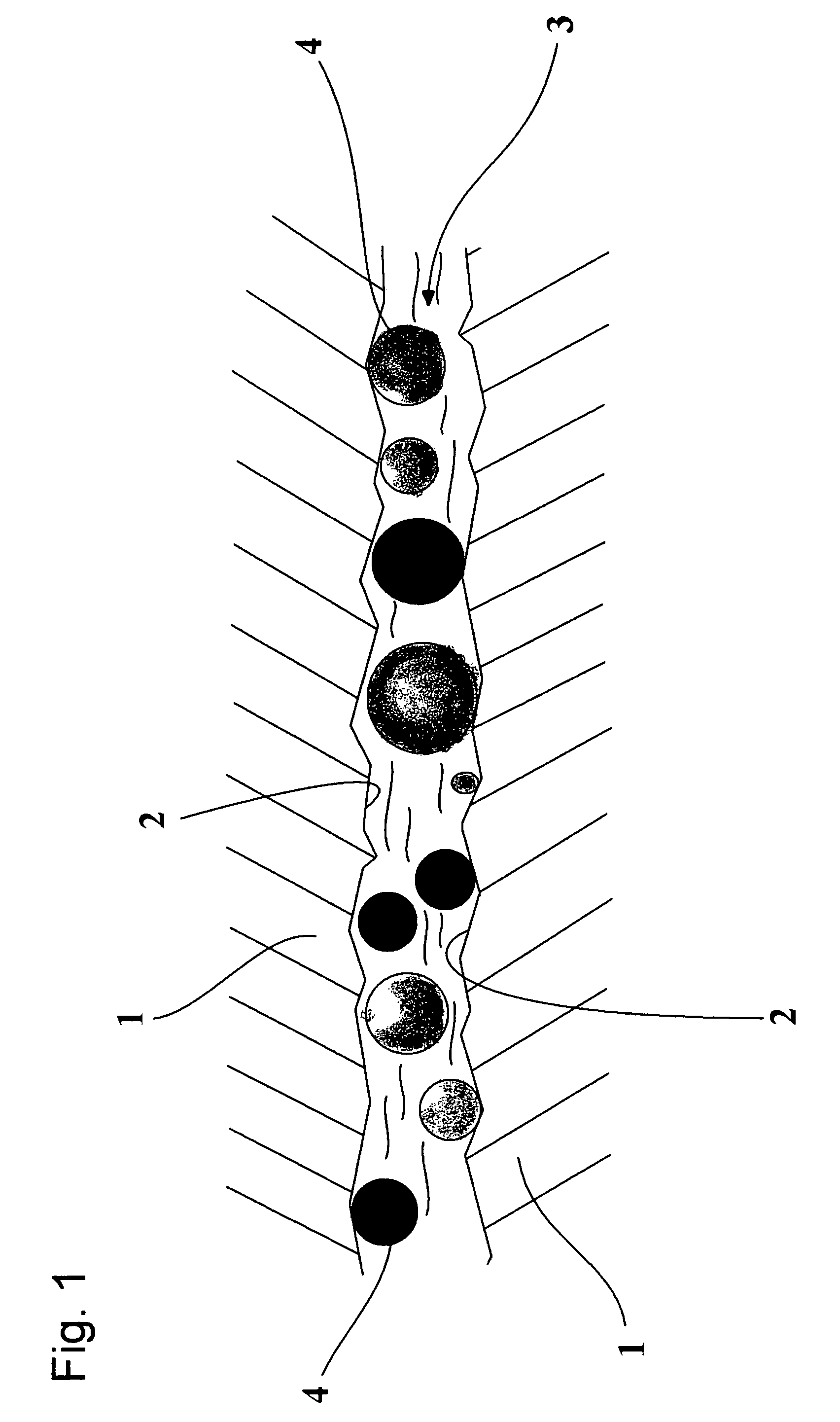
[0039]Next, a description will be given of one example to which the present invention is applied, and results of actual measurement thereof with reference to FIGS. 7 to 9, thereby viewing an effectiveness of the present invention. The structure of the present embodiment is made such that a middle-speed diesel engine for a ship at 750 rpm to the maximum is provided with a shaft 5 for transmitting a power of the engine and applying a rotation force to a screw, and a bore 7 formed in a cylindrical shape by bonding two semicircular arc metal parts 6 for bearing and axially supporting the shaft 5, and is provided with the lubricating oil 3 interposed in the friction surface 2 between the bore 7 and the shaft 5, and the insoluble content 4 contained in the lubricating oil 3, and the bore 7 in accordance with the present embodiment has a three-layer laminated structure constituted by an overlay layer 8, a nickel dam layer 9 and a lead bronze layer 10 as shown in FIG. 6.

[0040]FIG. 8 shows t...

embodiment 3

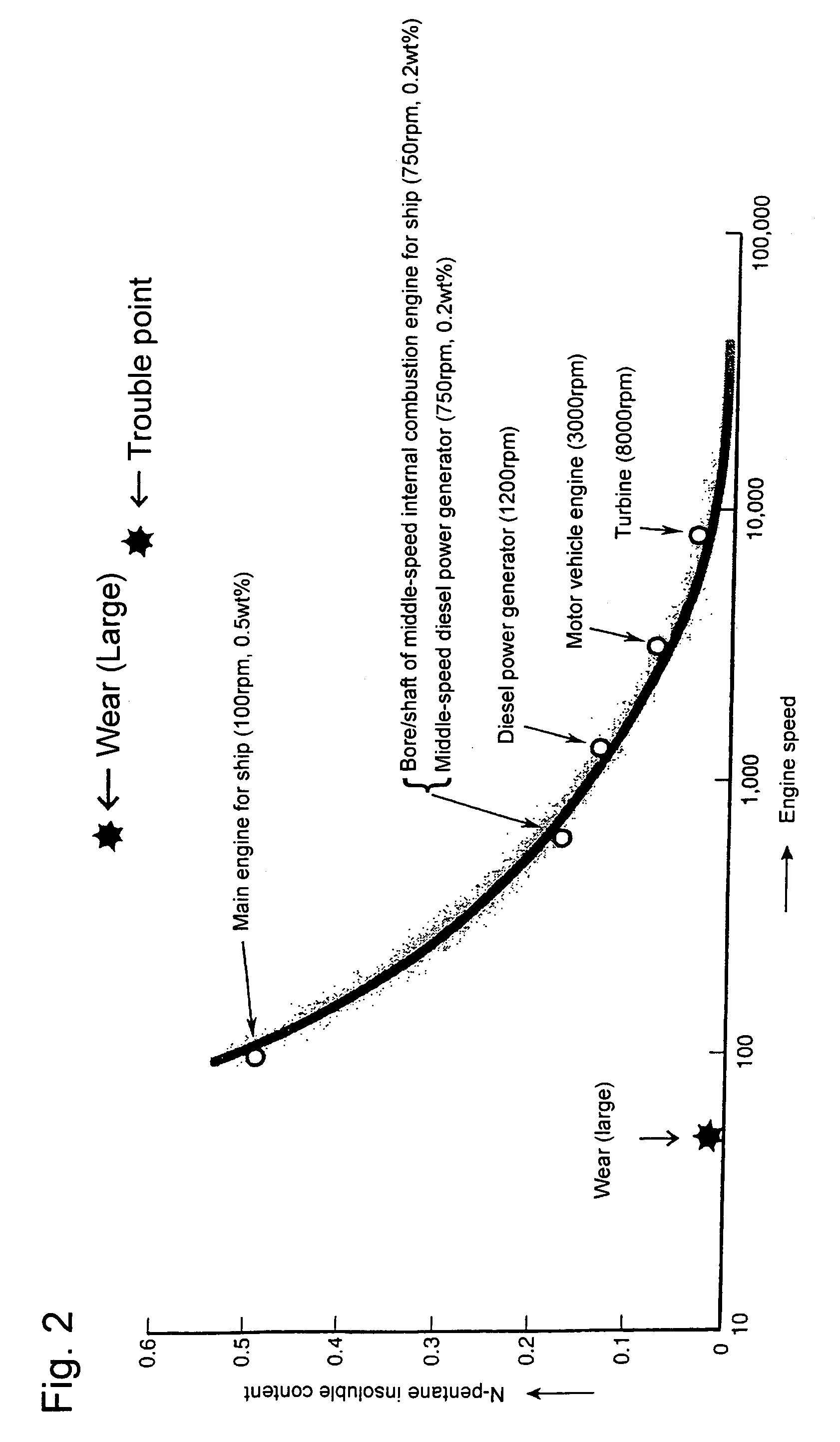
[0045]Further, there is shown the results of an actual device test executed by the inventors with using a four-cycle supercharged diesel six-cylinder engine (1544 kW×800 rpm, D×S=370 mm×540 mm) equipped with the precise filtering means mounted on a training ship, HOKUSEIMARU, of Faculty of Fisheries of Hokkaido University commissioned on October, 1976. In accordance with the result, the lubricating oil nature was kept approximately constant during the operation over 18000 hr in about ten years up to October, 1987 when a secondary intermediate inspection was executed, and the percentage content of the n pentane insoluble content was kept in a fixed value about 0.2 mass %. Since the lubricating oil was kept clean as in the result, the engine was kept clean and a red paint was left in a crank chamber such as just after manufacturing. The wear during the ten years is 0.008 mm / 1000 hr in the liner, and 0.014 / 1000 hr in the ring which correspond to one fifth to one tenth of the normal one...


PUM


Abstract

An object of the invention is to provide a system for suppressing a wear due to a friction of a friction system between two objects, particularly suppressing a wear due to a friction between a cylinder and a piston in an internal combustion engine to the minimum, increasing a reliability of the internal combustion engine to the maximum, and extending an interval of an overhaul to the maximum. The system is characterized in that an insoluble content is regulated in correspondence to the maximum rotation speed of a relative motion so as to be within a range of a specific optimum percentage content with respect to a lubricating oil so as to be contained, and is maintained, in a friction system in which the lubricating oil is interposed between two objects for the purpose of suppressing a wear due to a friction of a friction surface in a contact periodical relative motion between the two objects.

Description

TECHNICAL FIELD[0001]The present invention relates to a technique of suppressing a wear due to a friction by interposing a lubricating oil in a friction surface of a friction system between two objects, and more particularly to a technique of improving a reliability of an internal combustion engine by suppressing a wear due to a friction between a cylinder and a piston in the internal combustion engine.BACKGROUND ART[0002]It is considered that a factor of the wear in the friction system between two objects is a friction between the objects. Accordingly, it has been conventionally considered that the wear is absorbed by interposing the lubricating oil between the objects, for example, between the cylinder and the piston in the internal combustion engine, whereby the wear is suppressed. In fact, it is apparent from experience that the wear is reduced by interposing the lubricating oil. However, the wear can not be completely prevented by interposing the lubricating oil in the friction...

Claims


Application Information

Patent Timeline
Patent Type & Authority Patents(United States)
IPC IPC(8): F16N39/00F01M9/02C10M171/00C10M177/00F01M9/00F16C33/10F16J10/02F16N39/06
CPCC10M171/00C10M177/00F01M9/00C10N2230/06C10N2240/10C10N2030/06C10N2040/25F01M9/02F16C33/10F16J10/02F16N39/00
Inventor SUMIMOTO, MORIO
Owner SUMIMOTO SCI INST CO LTD
Why Eureka
Eureka Blog
Learn More