Electronic device and method for adjusting settings thereof

a technology of electronic devices and settings, applied in the direction of electric digital data processing, instruments, computing, etc., can solve the problems of unpleasant experience for users using the projector frequently, inconvenient control, etc., and achieve the effect of reducing trouble, finishing the adjustment quickly, and saving tim

Inactive Publication Date: 2012-05-03
ASUSTEK COMPUTER INC
View PDF7 Cites 42 Cited by
  • Summary
  • Abstract
  • Description
  • Claims
  • Application Information

AI Technical Summary

Benefits of technology

[0008]The invention discloses an electronic device and a method for adjusting settings thereof. By improving or integrating software or hardware, the user may directly and intuitively adjust the image, which saves labor, time and cost, and increases competitiveness and efficient.
[0014]Therefore, in the electronic device of the invention and the method for adjusting the settings thereof, multiple main setting menu keys are disposed on the user interface, and the user may intuitively select the frequently-used options and finish the adjustment quickly. This not only saves time, but also reduces the trouble in looking for the key one after another after a single menu key is pressed.
[0015]In addition, the user interface in the invention may also include a control unit which may be operated in a pressing or sliding mode to replace the conventional cross directional key. The control unit cooperates with a graphical user interface and main setting menu keys to make the adjustment smoother, and the user also may adjust the images at his will. The electronic device and the method for adjusting the settings thereof include a human-friendly control interface, and comparing with the conventional electronic device, the invention is more intuitive.
[0016]When the invention is used in a projector, since the projected screen, the distance, the image content, the size and so on are not fixed, it is a necessary step to set the projector before the projector is used. The technique in the invention may help the user to finish the adjustment quickly and correctly, and therefore the user may not feel troublesome in using the projector.

Problems solved by technology

However, obviously, when the control interface 11 is operated, the user has to look for the option which needs to be adjusted line by line, which is inconvenient in controlling.
Sometimes, the adjusted image is small, and the user may wrongly watch or select the option, and he may not finish the adjustment quickly, which is an unpleasant experience to the user using the projector frequently.

Method used


Image

  • Electronic device and method for adjusting settings thereof
  • Electronic device and method for adjusting settings thereof
  • Electronic device and method for adjusting settings thereof

Examples


first embodiment

[0042]FIG. 3 is a schematic diagram showing the electronic device in the invention. As shown in FIG. 3, the electronic device 3 includes a casing 31, a user interface 32, a processing unit 33 and an image output unit 34.

[0043]The user interface 32 is disposed on a casing 31, and it may be disposed on the electronic device 3. The processing unit 33 is disposed in the casing 31 and connected to the user interface 32. The processing unit 33 processes the signal input from the user interface 32, and performs the corresponding controlling function. In addition, the image output unit 34 may be disposed at the front of the electronic device 3 for outputting an image F. However, in other embodiments of the invention, the user interface 32 also may be connected to the electronic device 3 in a wireless transmission mode, and it may not be disposed at the casing 31.

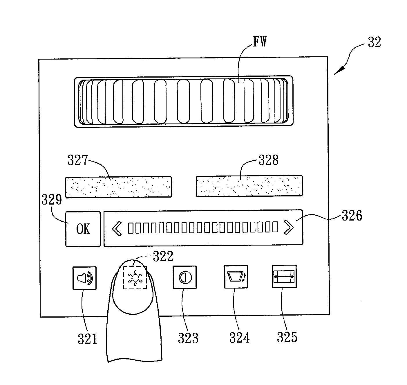
[0044]FIG. 4 is an enlarged diagram showing the user interface of the electronic device in FIG. 3. As shown in FIG. 4, the user in...

second embodiment

[0070]FIG. 11A is a schematic diagram showing the movement that the user operates the control unit to adjust the main setting value in the invention. FIG. 11B and FIG. 11C are schematic diagrams showing the displayed main setting option image corresponding to the movement in FIG. 11A.

[0071]As shown in FIG. 11A, the user generates the touch displacement event to the control unit 326′ (the finger moves in curve lines on the control unit 326′) to adjust the main setting value, and the user's sliding operation is the single point clockwise sliding.

[0072]Therefore, when the user slides his finger from the position A′ to the position B′ on the control unit 326′, the displayed main setting value (brightness) in the main setting value display area 351′ of the main setting option image 35′ increases (comparing with that in FIG. 11B and FIG. 11C), and the image outputted by the electronic device is brighter. On the contrary, in the same main setting options, if the sliding operation is the si...

third embodiment

[0100]FIG. 17 is a flow chart showing the method for adjusting the settings of the electronic device in another embodiment of the invention. As shown in FIG. 17, in the embodiment, the method for adjusting the settings of the electronic device is adapted to the electronic device in the invention to allow the user to adjust the outputted image. The adjusting method includes the following steps.

[0101]In step S170, providing a user interface with multiple main setting menu keys and a control unit;

[0102]In step S171, selecting one of the main setting menu keys to call a main setting value corresponding to the main setting menu key;

[0103]In step S172, outputting a corresponding main setting option image according to the main setting value, and the main setting option image includes a main setting graphical user interface and a main setting value display area;

[0104]In step S173, providing a touch event to operate the control unit and adjust the main setting value;

[0105]In step S174, selec...


PUM


Abstract

A method for adjusting settings of an electronic device is disclosed. The method includes the steps as follows: providing a user interface including a plurality of main setting menu keys and a control unit; selecting one of the main setting menu keys to call a main setting value corresponding to the main setting menu key; outputting a corresponding main setting option image at least including a main setting value display area according to the main setting value; and providing a touch control event to operate the control unit for adjusting the main setting value and then display the adjusted main setting value on the main setting value display area. The touch control event includes a touch displacement event and a touch event. The method for adjusting the settings is contemplated for user's intuitive operation to save the time cost.

Description

BACKGROUND OF THE INVENTION[0001]1. Field of Invention[0002]The invention relates to an electronic device and a method for adjusting settings thereof and, more particularly, to an electronic device suitable for intuitive operation and the method for adjusting the settings thereof.[0003]2. Related Art[0004]With the progress of science and technology, people would like to use an electronic device instead of papers to output images. The electronic device becomes to be the most common operation and communicating media. Since the objectives of usage are different, and the image content varies, an electronic device usually includes a controlling interface to allow the user to adjust the settings, thereby making the outputted image clear and suitable for watching for a long time.[0005]FIG. 1 is a schematic diagram showing a conventional projector. FIG. 2A is a control interface of the projector in FIG. 1. FIG. 2B is a schematic diagram showing that the settings of the projector are adjuste...

Claims


Application Information

Patent Timeline
Patent Type & Authority Applications(United States)
IPC IPC(8): G06F3/048
CPCG06F3/0482G06F3/04883G06F3/04847
Inventor CINDY, LIEW HUI MINLYNN, NG WANJIE, LIONEL WONG ZHENHUNG-HSIANG, CHENALENQUER, DANIEL PITTELLAFONG, LOI WEANWONG, ALECCHIA-CHENG, SHIHQIN, LEE YUN
Owner ASUSTEK COMPUTER INC
Why Eureka
Try Eureka