

Mouth-operated moveable apparatus
a technology of moving apparatus and mouth, which is applied in the direction of theatre/circus, entertainment, art equipment, etc., can solve the problems of obstructing normal speech and difficulty in using the tongue to operate the mechanism
- Summary
- Abstract
- Description
- Claims
- Application Information
AI Technical Summary
Benefits of technology
Problems solved by technology
Method used
Image

Examples
first embodiment
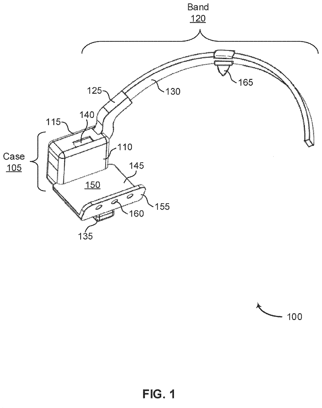
[0027]FIG. 1 shows an example of a perspective view of a mouth-operated moveable apparatus 100, in a first position, in the present invention. The example shown includes mouth-operated moveable apparatus 100 and accessory 165.
[0028]Referring first to FIG. 1, a perspective view of a mouth-operated moveable apparatus 100 in a first position is shown. The mouth-operated moveable apparatus 100 comprises a case 105 and a curved band 120 moveably coupled to the case 105. Each case 105 comprises a case body 110, a case cover 115, a mechanism, and an actuator foot 135. A first end of the band 120 comprises a band anchor 125, which is coupled to the mechanism. A second end of the band 120 is a free end. The mechanism includes a biasing element to automatically hold the first end of the band 120, which is coupled to the mechanism, in the first position. In the first embodiment, the first position results in a portion of the band 120 distal to the case 105 located upwards relative to the case ...
case 205
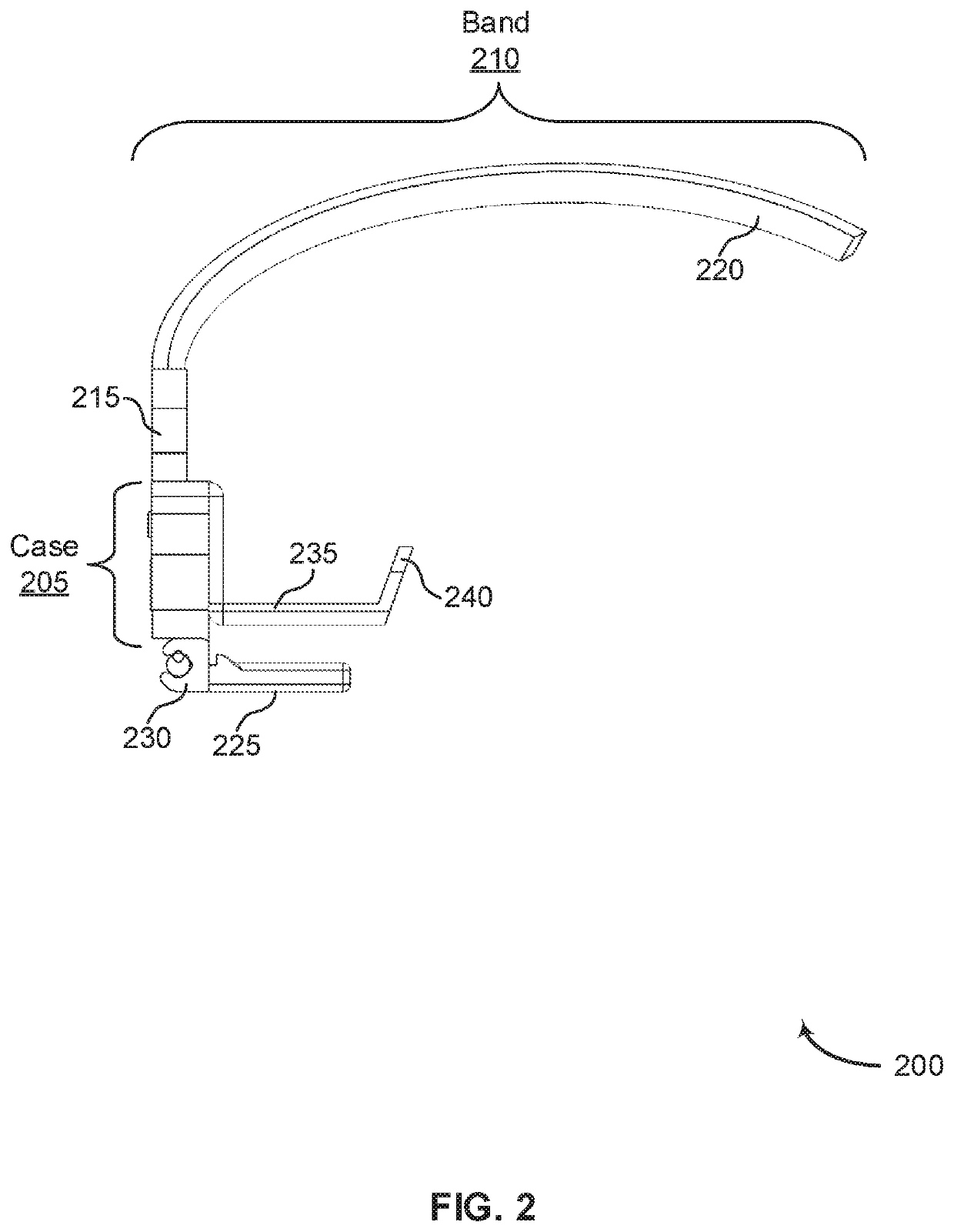
[0048]Case 205 may be an example of, or include aspects of, the corresponding element or elements described with reference to FIGS. 1, 4-8, and 11-13.
[0049]Band 210 may include band anchor 215 and band arm 220. Band 210 may be an example of, or include aspects of, the corresponding element or elements described with reference to FIGS. 1, 4, 6, 8, and 13. Band anchor 215 may be an example of, or include aspects of, the corresponding element or elements described with reference to FIGS. 1, 4, 6-8, and 11-13. Band arm 220 may be an example of, or include aspects of, the corresponding element or elements described with reference to FIGS. 1, 8, and 13.
[0050]Actuator foot 225 may be an example of, or include aspects of, the corresponding element or elements described with reference to FIGS. 1, 3, 4, 8, 11, and 13. Clip 230 may be an example of, or include aspects of, the corresponding element or elements described with reference to FIG. 3.
[0051]Bite plate 235 may include bite plate flange...
case 405
[0069]Case 405 may include case cover 410 and case body 415. Case 405 may be an example of, or include aspects of, the corresponding element or elements described with reference to FIGS. 1, 2, 5-8, and 11-13. Case cover 410 may be an example of, or include aspects of, the corresponding element or elements described with reference to FIGS. 1, 5, 8, 11, and 13.
[0070]Case body 415 may include top opening 420 and slide opening 425. Case body 415 may be an example of, or include aspects of, the corresponding element or elements described with reference to FIGS. 1, 6, 8, and 11-13. Top opening 420 may be an example of, or include aspects of, the corresponding element or elements described with reference to FIGS. 7 and 8. Slide opening 425 may be an example of, or include aspects of, the corresponding element or elements described with reference to FIGS. 7 and 8.
[0071]Band 430 may include band anchor 435. Band 430 may be an example of, or include aspects of, the corresponding element or el...
PUM
 Abstract
Description
Claims
Application Information